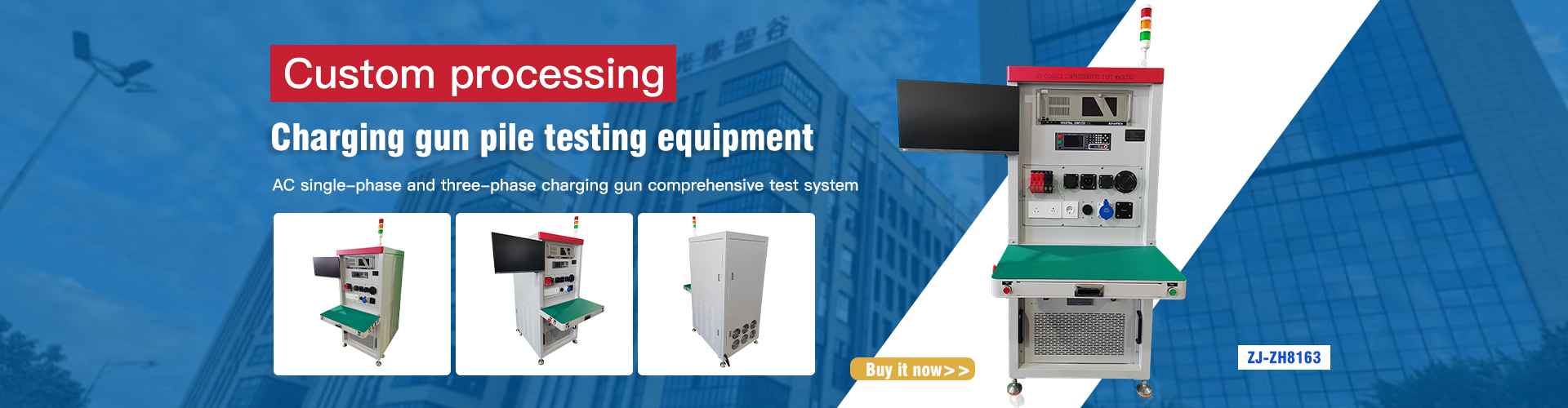
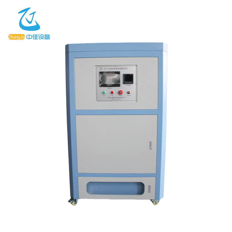
products
HomeOur ServicesInrush Current

Inrush Current

ZJ-YL300A
The impulse current tester produced by our company is made in accordance with the requirements of the standard IEC61851-1: 2017-02, version 3.0 Electric vehicle conductive charging system Part 1: General requirements Chapter 12.2.6.
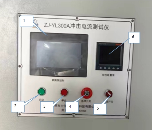
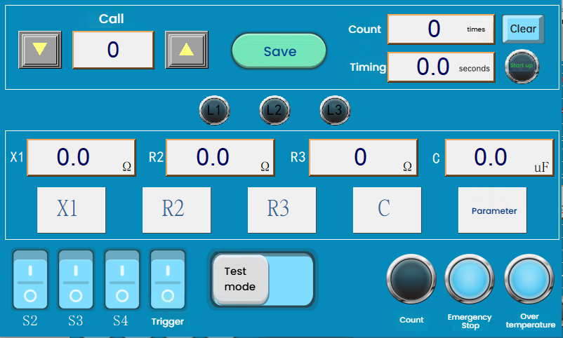
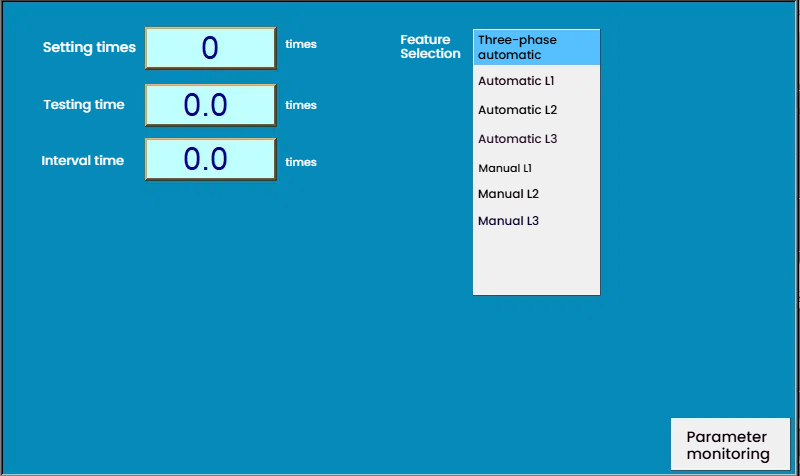
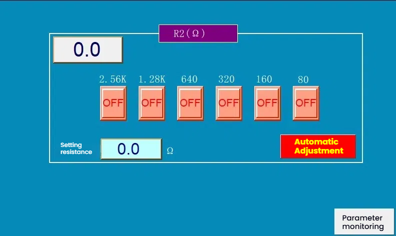
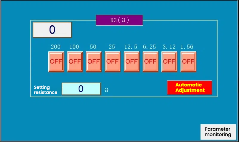
The equipment is controlled by PLC+touch screen.
Meet the following standards:
According to ISO 17409: 2015 Section 8.2.2, AC electric vehicle supply equipment should be able to withstand surge current.
The following values are specified in ISO 17409:
• After closing the contactor in the electric vehicle supply equipment at the peak value of the supply voltage, the electric vehicle supply equipment should be able to withstand a peak of 230 A for a duration of 100µs.
• In the next second, the electric vehicle supply equipment should be able to withstand 30 A (RMS).
According to /EC TS 61439-7, compliance with this requirement can be verified by testing the entire electric vehicle supply equipment or a single switch device.
The protection device should be selected so that it will not trip due to the inrush current.


Panel Description

Figure 2 Control Panel
1. Touch screen: parameter setting and monitoring.
2. Start button: machine start.
3. Stop button: machine stop.
4. Emergency stop switch: equipment emergency stop operation.
5. Power switch: control power switch.
6. Comprehensive electricity meter: display load voltage, current, power factor.
Figure 3 Front
Load power supply output terminal: sample power supply port
Load resistor output terminal: sample output load wiring port
Trigger signal port: charging pile trigger terminal wiring port (S2 switch loop)
Operation Instructions
7.1 The equipment load power supply is connected to the external AC380V power supply. The control power supply is connected to the AC220V mains. Figure 5 below
Sample wiring: connect the sample to the sample wiring port. The load power supply output terminal supplies power to the sample. The load resistor output terminal provides a load to the sample output terminal. At the same time, connect the oscilloscope to the sample output terminal Ln.
Turn on the panel power switch. Touch screen enters the test interface of Figure 6:
Figure 5
Figure 6
S 2: Push up manually, trigger signal E1/E2 is turned on
S 3: Push up manually, connect the main load resistor
S 4: Push up manually, connect the compensation load resistor
Trigger: Push up manually, the voltage is turned on at 90 degrees
X1: Main load resistor
R2: Compensation load resistor
R3: Peak current loop resistor
C: Peak current loop capacitor
Call: Switch the set formula through the up and down keys, press Save and call it out for use.
Save: Save the set formula in the database of the corresponding serial number
Count: Number of tests
Reset: Clear the number of tests
Timing: Power on or off timing
L1/L2/L3 indicator light: Select the phase line indicator light for the test. When L1 phase is selected, the L1 light flashes or lights up.
Counting light: The indicator light flashes when the count reaches the set number.
Emergency stop light: Press the emergency stop switch and the machine stops. The indicator light flashes.
Over temperature light: The indicator light flashes when the temperature exceeds the set temperature value.
7.2 Manual adjustment Click Parameter to enter the parameter setting interface, see Figure 7 below. Select automatic L1 phase. Set the number of tests, test time and interval time.
Figure 7
Three-phase automatic: L1 phase, L2 phase, L3 phase are tested in sequence. One cycle counts once.
Automatic L1: Test L1 phase until the set number of times
Automatic L2: Test L2 phase until the set number of times
Automatic L3: Test L3 phase until the set number of times
Manual L1: Test L1 phase once
Manual L2: Test L2 phase once
Manual L3: Test L3 phase once
Close the load power switch (Figure 3). At this time, the load power output terminal outputs 380V voltage to supply 30A current to the equipment. Click the R3 peak loop resistance button to enter the R3 interface and turn off all resistance switches in this interface (turning the switch to OFF can turn off the resistance of this channel) See Figure 8 below. Toggle the S3 switch up to turn on the S3 main load resistance switch. Click the X1 main load resistance button to enter the main load interface to set the resistance. Figure 9 below
Figure 8
Figure 9
This interface allows you to manually adjust the resistance level or automatically adjust the resistance. If you don't know how much resistance you need, you can generally choose manual adjustment. For example: manually press several resistance gears, the resistance gear displays ON, (automatic adjustment: Under the condition of knowing the resistance value, set the resistance box to enter the appropriate resistance, and then press the right test automatic adjustment button. At this time, the resistance gear is automatically adjusted to the appropriate gear. Press the panel start button. Observe the current value of the integrated power meter on the control panel. Adjust the resistance in the main load X1 until the current reaches 30A. When the current can only be close to 30A, the current can be compensated to reach 30A. After turning on the compensation switch S4 in the test interface, click the R2 button to enter the compensation resistance interface, as shown in Figure 10
Figure 10
Select the appropriate resistance gear and press the start button again. Make the current reach 30A.
200A current pre-adjustment test interface After turning off the S3 and S4 switches, click the peak loop resistance R3 button to enter the R3 resistance interface (Figure 11), and select the appropriate resistance gear switch (set the switch to ON). Click the peak capacitance C button to enter the capacitance interface (Figure 12), and select the appropriate capacitance gear switch (set the switch to ON). At this time, press the control panel start Button. The oscilloscope outputs waveform. Adjust the Peak Loop Resistance R3 position switch and the Peak Loop Capacitance C position switch. Until the desired waveform is reached.
Figure 11
Figure 12
Open the pre-adjusted main load resistance switch S3 and compensation resistance load S4 above, and use the up or down button to select the appropriate formula name. Press the control panel Start button again, and then observe that the waveform of the oscilloscope reaches 230A. Press the Save button to save the current formula
Note: The above is a detailed operation method. The machine has been set with a 230A current formula (0~3 formulas) when it leaves the factory. After connecting the product, push switches S2 and S3 up, and press the panel Start switch to perform the inrush current test
7.3 Test Enter the parameter setting and select the test process. Call out the set formula. Turn on the S2 and S3 switches. Press the panel Start button, and the device starts outputting current test. Stop when the test number is reached.
1. Instrument power supply: single-phase 220V/50HZ.
2. Control external sample voltage: single-phase 220V, (sample power supply is provided by the user)
2. Peak current: 230A, rated current 30A.
3. Current measurement time: within 100 us after power failure.
×

Contact Us

captcha