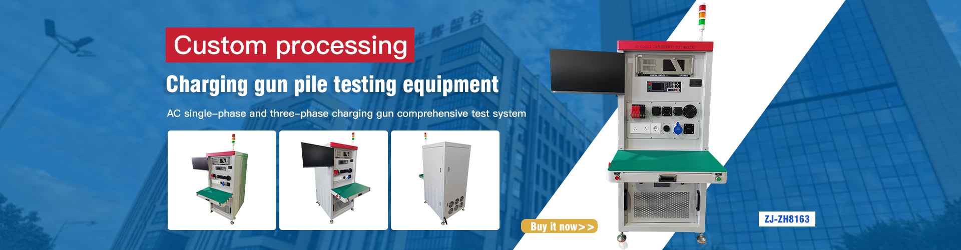
1. Applicable products
Used for aging test of single-phase AC charging gun pile to ensure that the product shipment meets the requirements. Applicable to aging test of electric vehicle AC charging gun/pile products that comply with GB/T 18487.1-2015, IEC 62196-2-2016, SAE J1772-2017, SAE J1772-2017. The actual product is shown in the figure below:
Standard: single-phase three-phase national standard, European standard, American standard
Load voltage: single-phase AC 0~300V three-phase 0~420V (external input, power supply provided by the user)
Load current: 1~32A continuously adjustable
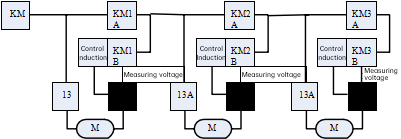
2. Test schematic diagram
The test schematic diagram is shown in the figure below. KM represents contactor, 13A represents AC socket, black square represents AC charging gun holder, control guide is control guide module, and M2 represents AC charging gun mode 2.
3. Test control principle
Device wiring schematic diagram, taking 10 products as an example, the back end is connected in series. The maximum number of tests is limited by the maximum allowable range of voltage drop. This device has 2 groups, each group of 10 products is tested online at the same time. Note: KMXA and KMXB are interlocked wiring and cannot be pulled in at the same time.
Brief introduction to the working principle of the electrical appliance:
Station 1, insert the product, KM contactor energizes, M2 product is powered on, and charging starts by controlling and guiding S2. If the product at station 1 is charged normally, KM1B is energized and KM1A is disconnected. If charging is not possible or there is no product, KM1A is energized and KM1B is disconnected, and electricity is directly transmitted to station 2.
Station 2, insert the product, KM contactor energizes, M2 product is powered on, and charging starts by controlling and guiding S2. If the product at station 2 is charged normally, KM2B is energized and KM2A is disconnected. If charging is not possible or there is no product, KM2A is energized and KM2B is disconnected, and electricity is directly transmitted to station 3.
And so on...
Station 12, insert the product, KM contactor energizes, M2 product is powered on, and charging starts by controlling and guiding S2. If the product at station 2 is charged normally, then KM12B is energized, KM12A is disconnected, and if charging is not possible or there is no product, KM12A is energized, KM12B is disconnected, and the power is directly transmitted to the load contactor.
The power meter measures the aging voltage and aging current of the product to be tested in turn, and stops aging if a defect is found.
4. Feedback load
The load adopts a feedback load, which is also called an energy feedback type electronic load. Compared with ordinary resistance loads, its working mode is to use power electronic conversion technology to recycle the output energy of the power supply to be tested on the premise of completing the test power experiment, and feed the electric energy back to the power grid without pollution, which saves energy and does not generate a lot of heat, avoiding the problem of rising ambient temperature in the test site.
5. Software
The system software has a one-button test, and all the test results can be recorded and queried. It has a QR code scanning function, which can trace the product test data. The operating table is designed according to ergonomics, and the equipment can perform self-test.
(1) The operating software uses a Chinese interface, which is simple and easy to learn.
(2) Computerized operation, all tests are completed at one time
(3) Can be connected to the MES system
(4) Scan code test
(5) Test data traceability
(6) Test data can be automatically saved as EXECL or TXT files
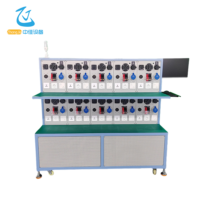
Complete machine pictures
Pictures are for reference only, the actual product shall prevail (Figure 1)
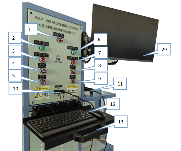
Panel Description
Figure 1
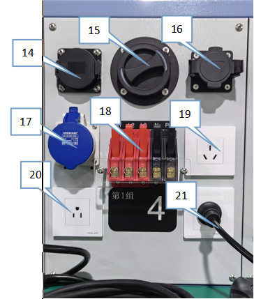
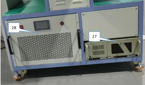
Figure 2
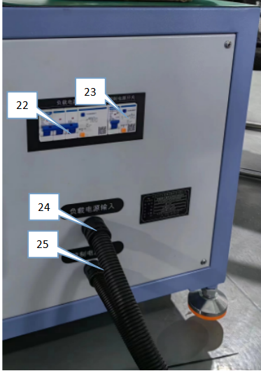
Figure 3
Figure 4
①&emsp.Main power switch of the whole machine
②&emsp.Start Group 1
③&emsp.Stop Group 1
④&emsp.Single-phase and three-phase mode switching of Group 1
⑤&emsp.Power on Group 1
⑥&emsp.Start Group 2
⑦&emsp.Stop Group 2
⑧&emsp.Single-phase and three-phase mode switching of Group 2
⑨&emsp.Power on Group 2
⑩&emsp.USB port
⑪&emsp.Scanner
⑫&emsp.Keyboard and mouse
⑬&emsp.Keyboard and mouse bracket
⑭&emsp.American standard gun end seat
⑮&emsp.European standard gun end seat
⑯&emsp.National standard gun end seat
⑰&emsp.European standard single-phase 32A socket
⑱&emsp.Line sequence terminals L1, L2, L3, N, PE
⑲&emsp.National standard 16A socket
⑳&emsp.American standard 15A socket
㉑&emsp.European standard 16A socket
㉒&emsp.Load power switch
㉓&emsp.Control power switch
㉔&emsp.Load power input
㉕&emsp.Control power input
㉖&emsp.Instrument nameplate information
㉗&emsp.Computer host
㉘&emsp.Three-phase feedback load box
㉙&emsp.Computer monitor
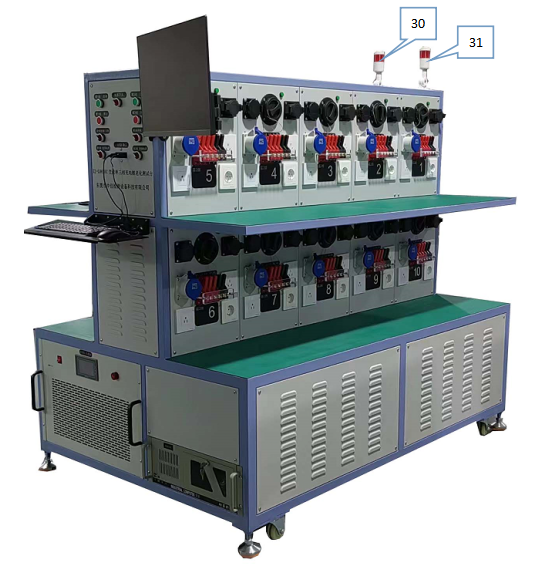
㉚&emsp.1st group alarm
㉛&emsp.2nd group alarm
Instructions
1. Power connection, connect the power input to the external power supply AC220 V, connect the three-phase load power input to the three-phase power supply, press the "power main switch" on the side panel, turn on the "power switch" knob on the control panel, and the machine will start. If you want to select the three-phase mode test, turn on the "single-phase, three-phase switching" switch at the same time.
2. After turning on the computer, enter the standby interface. Open the desktop test software, enter the test interface, manually enter the material number, scan the station barcode, and then press Enter to save, as shown in Figure 5
Figure 5
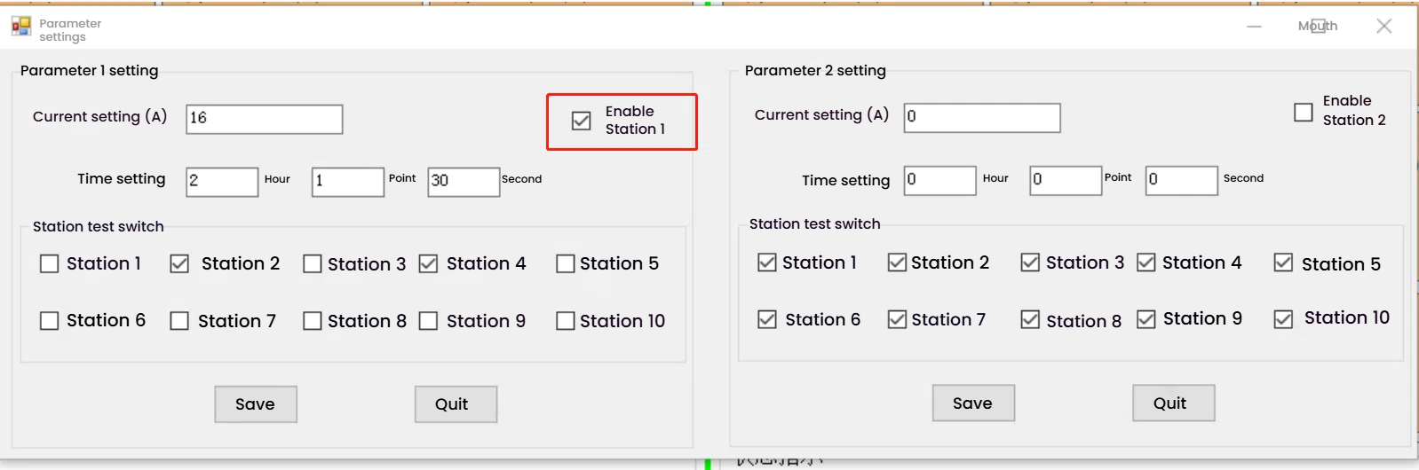
3. After installing the sample, click the upper left corner to enter the "Parameter Setting" interface, enter the corresponding "Parameter 1 Setting", set the current (ampere), set the test time, check the start station 1 (i.e. Group 1), turn on (check) the switch of the station to be tested, and click Save, as shown in Figure 6.
Figure 6
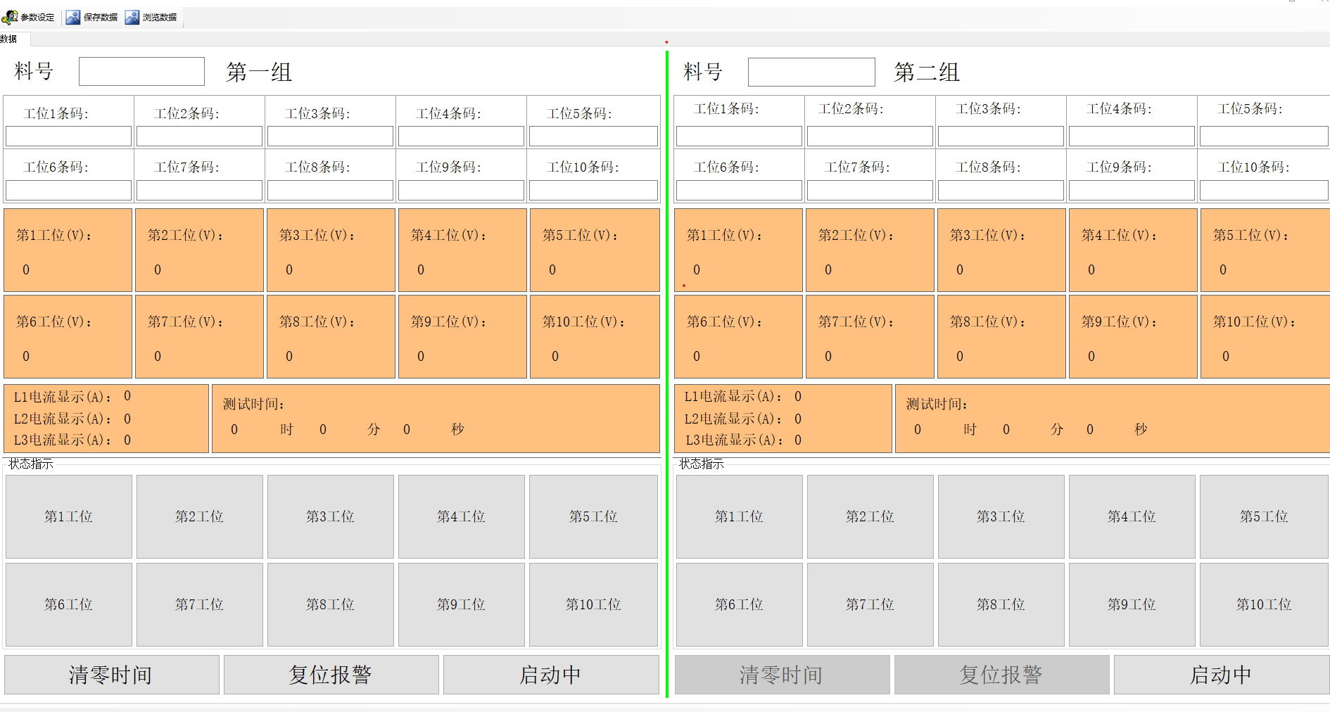
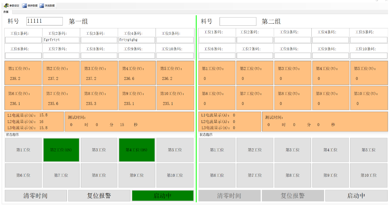
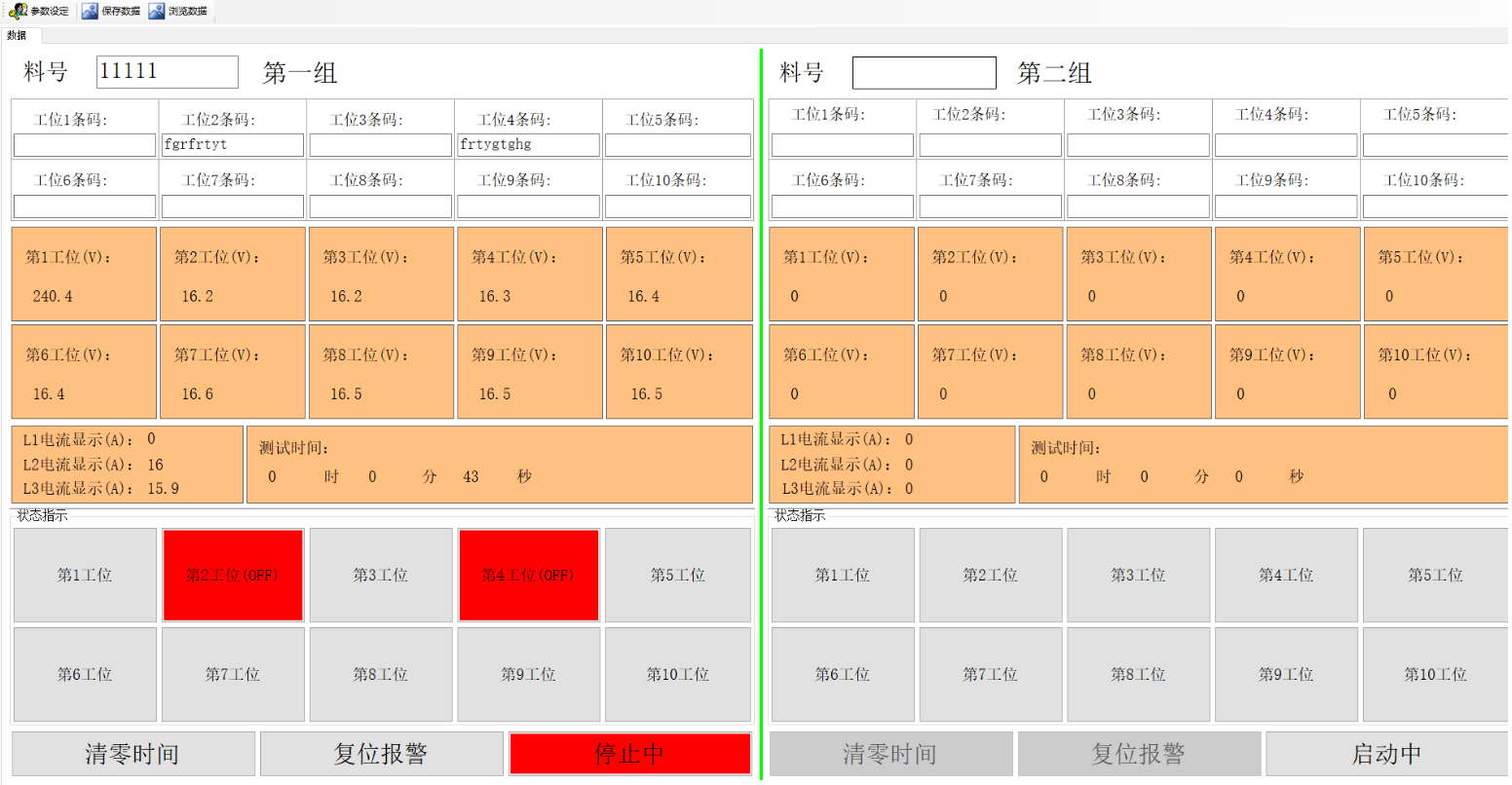
4. After setting the parameters in the previous step, press the "Start" button on the control panel to enter the start test interface and browse the data. If the current station is displayed in green, the test is qualified, and if it is displayed in red, the test is unqualified, as shown in Figure 7 and Figure 8.
Figure 7
Figure 8
Clear time: clear the set time.
Reset alarm: reset the alarm information.
Starting: start the test.
Stop: stop the test.
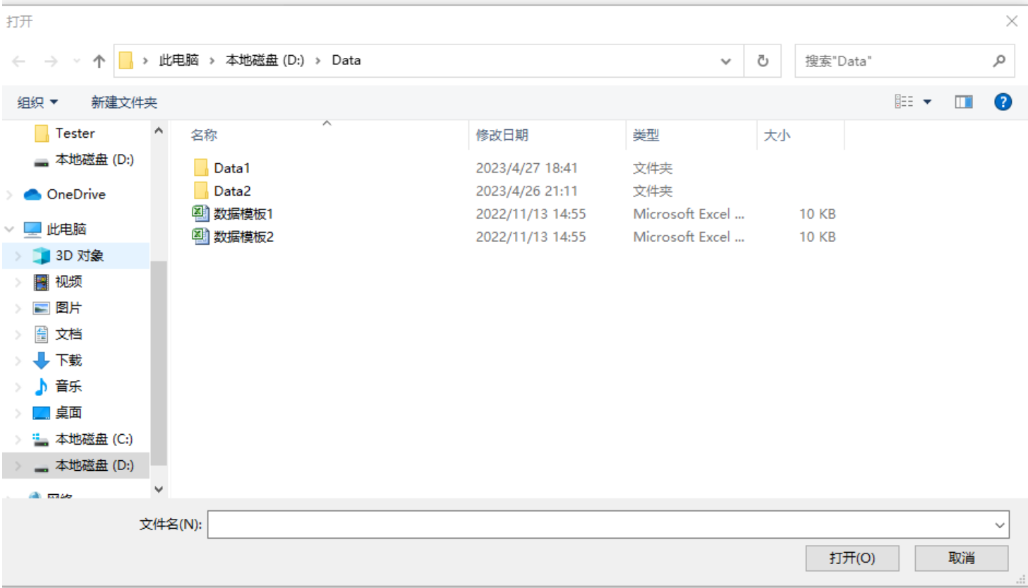
5. Save the data after the test, click "Browse Data" in the upper left corner, open Data1, as shown in Figure 9.
Figure 9
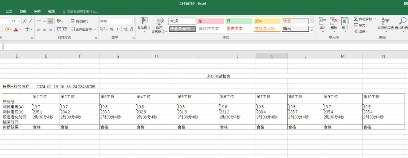
6. The test report is as follows:
1、Number of Workstations: 2 layers per group, 5 workstations per layer, totaling 2 back-to-back groups, with a total of 20 workstations.
2、Load Requirement: Each group is equipped with a 0-32A intelligent electric control load, using a regenerative load system.
3、Power Supply Socket: Each workstation is equipped with a terminal block.
4、One load circuit for every 10 workstations, totaling 2 load circuits.
5、Charging Gun Socket: Each workstation is equipped with single/three-phase AC charging gun sockets compliant with Chinese, American, and European standards.
6、Simulated Charging: Simulates the entire process from connecting the charging gun to charging.
7、Parameter Setting: An industrial computer management system allows free configuration of load current, test duration, and other parameters via the computer.
8、Storage Requirement: Aging data is automatically stored and linked to each product barcode, with electronic reports generated for printout.
9、Data Upload: Integration with the MES system enables data upload to the company's traceability system for real-time access.
10、Power Supply: AC220V/50Hz for operational power, AC380V/50Hz for aging power.
11、Equipment Dimensions: Length 1800mm × Width 1200mm × Height 1620mm.