Equipment functional index requirements
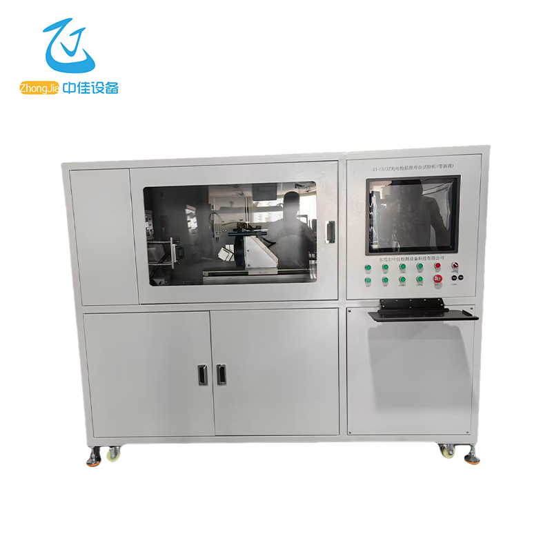
It is suitable for independently testing the plug-in life, plug-in force, and breaking capacity of a charging gun charging seat. It can automatically soak in 3 different solutions before plugging in and out. The test machine uses servo motors, linear modules, cylinders, etc. as power, and uses a small fixture to clamp the sample. The computer and imported programmable controller (PLC) are the control center. It can clamp the charging gun, automatically immerse the charging gun in rain acid solution, saline solution, and muddy water solution in turn, and then automatically take it out and insert it into the charging gun seat. The last power-on is 1.5 hours, and the action is repeated to simulate the plug-in life of the charging gun outdoors.
Usage Environment
1 | Ambient temperature | 5~35℃ |
2 | Ambient humidity | 85%R.H 25℃ |
3 | Atmospheric pressure | 86~106Kpa |
4 |
Environmental conditions | There is no strong vibration, no strong electromagnetic field interference, no high concentration of dust and corrosive substances, no direct sunlight or other direct radiation from heat sources around the equipment site. |
| | The equipment should be placed horizontally in a well-ventilated test room, with sufficient space around it for operation and maintenance. |
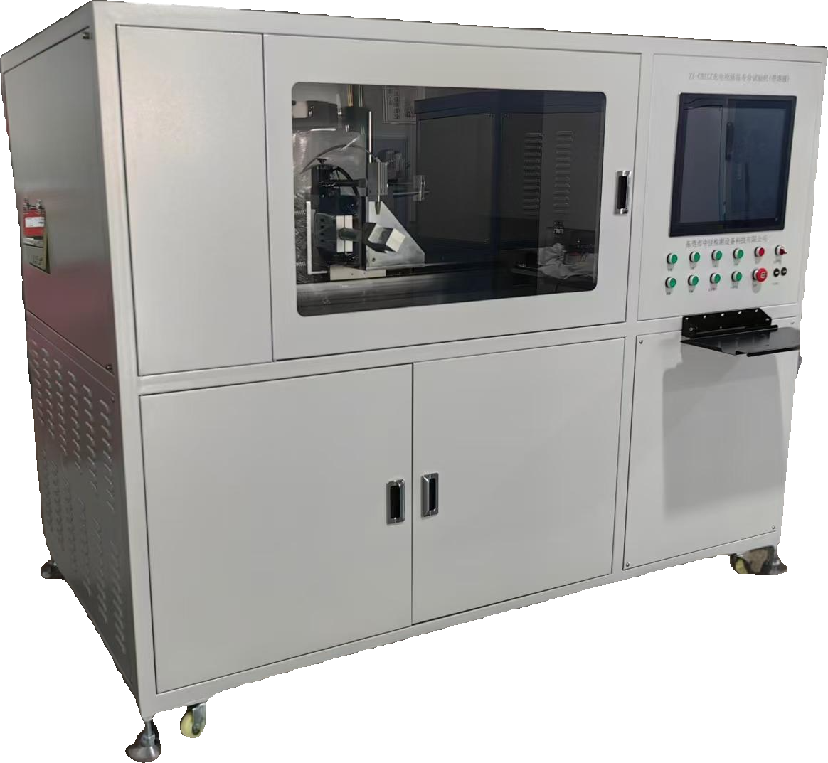
Machine picture
Main Figure (1) The picture is for reference only, the actual product shall prevail
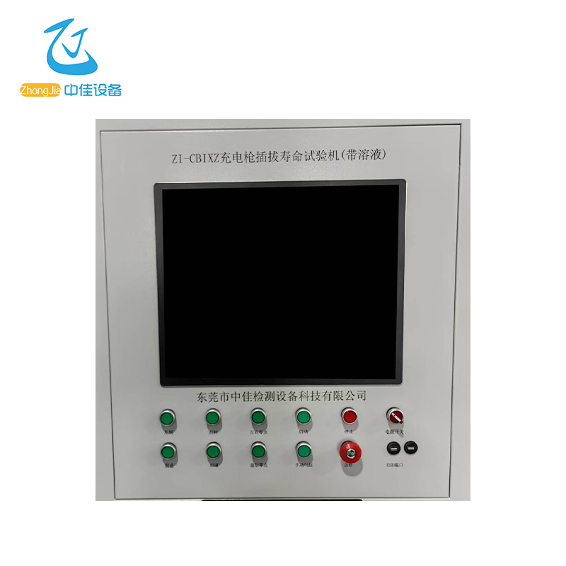
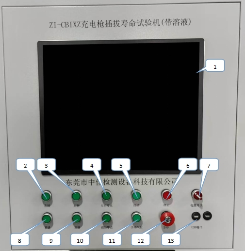
Panel Description
Figure 1
① Touch screen control: set parameters and monitor
② Left turn button: gun turns counterclockwise
③ Right turn button: gun turns clockwise
④ Left and right zero point buttons:
⑤ Start button: machine runs
⑥ Stop button: press to stop the machine
⑦ Power switch: switchboard power switch
⑧ Forward button: press the gun head fixture to move forward
⑨ Backward button: press the gun head fixture to move backward
⑩ Front and rear zero position:
⑪ Manual cylinder:
⑫ Emergency stop switch: emergency stop
⑬ USB port: connect keyboard, mouse, USB flash drive, etc.
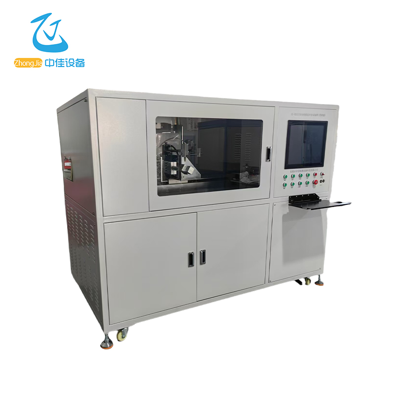
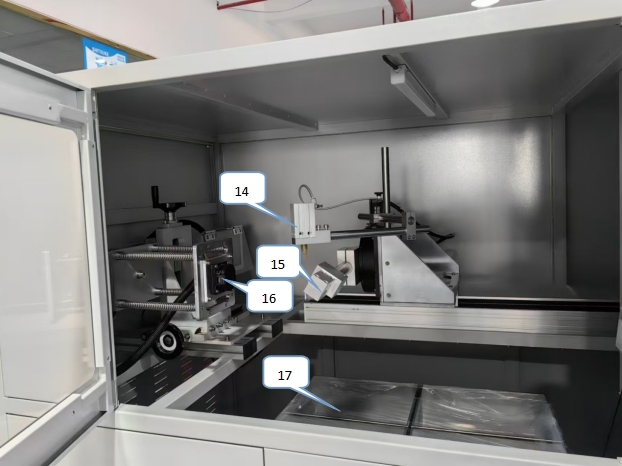
Figure 2
Figure 3
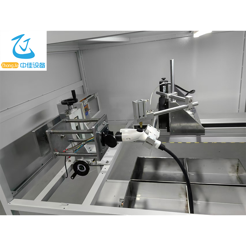
⑭ Press down cylinder: press cylinder
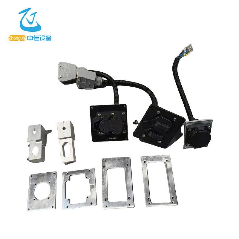
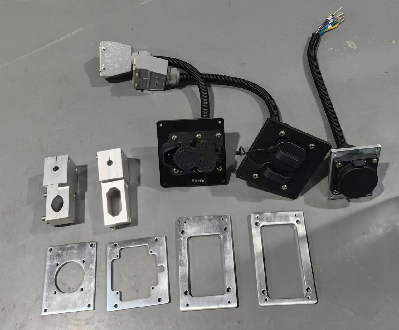
⑮ Charging gun holder sample installation
⑯ Charging gun head fixture
⑰ 4 liquid tanks (pour different solutions)
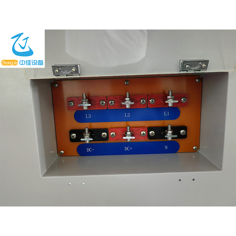
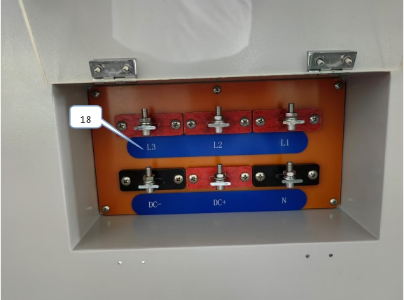
⑱ Gun holder wiring terminal: connect L1, L2, L3, N line sequence connection
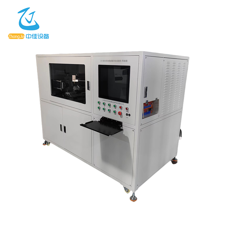
Figure 4
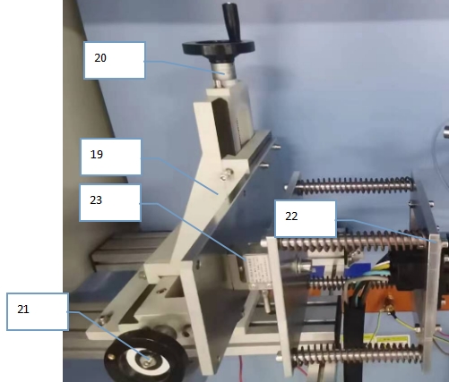
Figure 5
⑲ Working slide
⑳ Slide handwheel: upper and lower clamp adjustment
㉑ Slide handwheel: left and right clamp adjustment
㉒ Charging gun holder clamp
㉓ Pressure sensor
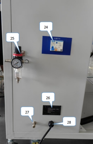
Figure 6
㉔ Power input leakage switch
㉕ Air source input: connected to the air pipe
㉖ Instrument nameplate information
㉗ Aviation connector:
㉘ Power input: connected to the power supply
Figure 7
Instructions for use
1. The power input on the side of the equipment is connected to the external AC220V control power supply, and the air source input is connected to the external 0.4~0.6MPa air pressure.
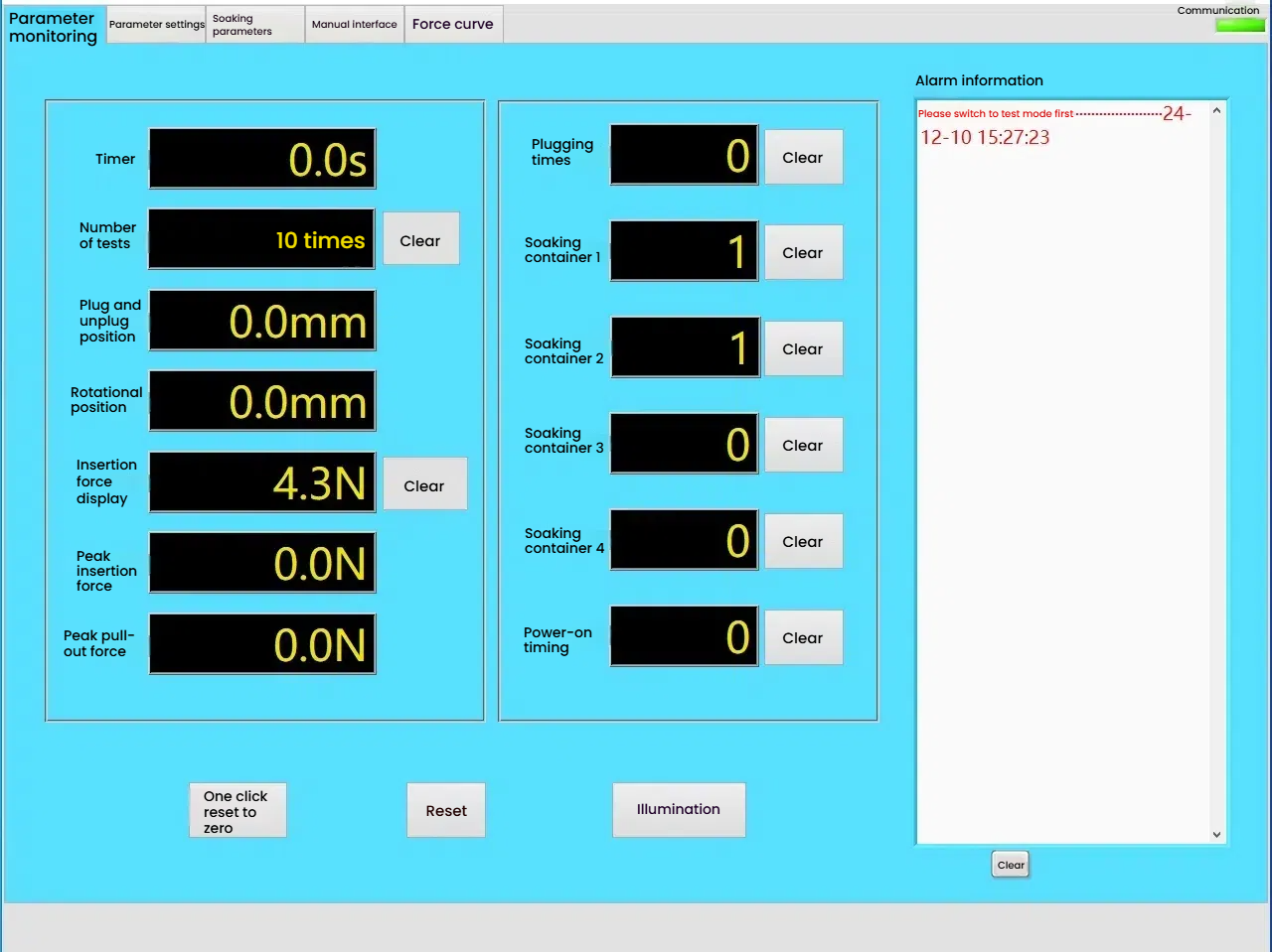
2. Turn on the panel "power switch" and double-click on the computer desktop to open the charging gun life test software.exe. Enter the touch screen "parameter monitoring" interface, as shown in Figure 8
Figure 8
Test times: Display the total number of tests
Reset: Reset the number of tests
Plug-in position: Display the current plug-in stroke (mm)
Rotation position: Display the current charging gun rotation angle value (degrees)
Plug-in force display: Display the real-time insertion force or extraction force (N)
Reset: Display force value reset
Insertion force peak value: Maximum instantaneous force value of insertion (N)
Pull-out force: Maximum instantaneous force value of pull-out (N)
Test process count (times)
Plugging and unplugging times: Display the current number of plugging and unplugging of charging gun
Immersion container 1: Display the current number of immersion times of container 1
Immersion container 2: Display the current number of immersion times of container 2
Immersion container 3: Display the current number of immersion times of container 3
Immersion container 4: Display the current number of immersion times of container 4
Reset button: Reset the current number of immersion times of container
One-key return to zero: Return to zero position
Reset button: Clear alarm information, reset the buzzer after the test is completed
Parameter button: Click to enter the parameter setting interface
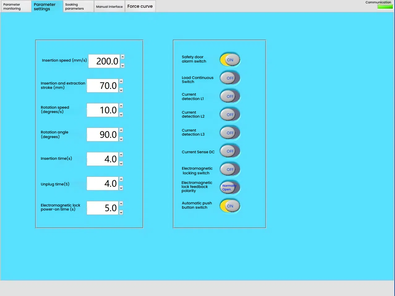
3. Enter the touch screen "Parameter Setting" interface: as shown in Figure 9
Figure 9
Plug-in speed: Set the plug-in speed (mm/s)
Plug-in stroke: Set the plug-in stroke MM (mm)
Rotation speed: Set the speed of charging gun rotation (degrees/second)
Rotation angle : Set the rotation angle of the charging gun (degrees)
Insertion time: The time for charging gun insertion can be set from 1 to 999.9s (seconds)
Unplug time: The time for charging gun to be unplugged can be set from 1 to 999.9s (seconds)
Electromagnetic lock power-on time: Set the power-on and power-off time of the electromagnetic lock from 1 to 999.9 (seconds)
Safety door alarm switch: Open the safety door to be effective, close the safety door to be invalid
Load continuous switch: Open the load continuous output, close the load intermittent output
Current detection L1: Detect L1 phase current
Current detection L2: Detect L2 phase current
Current detection L3: Detect L3 phase current
Current detection DC: Detect DC current
Electromagnetic locking switch: Open the electromagnetic lock to be effective, close the electromagnetic lock to be invalid
Electromagnetic lock feedback polarity: Open is a normally open signal, close is a normally closed signal
Automatic button press switch: Open the intermittent press gun head button, close is a long press gun head button
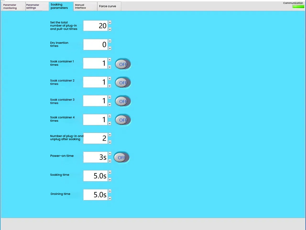
4, Enter the touch screen "Immersion parameters" interface Such as: Figure 10
Figure 10
Set the total plug-in and unplug times: the sum of the dry plug-in times and the soaking times 1~999999
Dry plug-in times: set the number of plug-in and unplug first 1~999999
Immerse container 1 times: set the soaking times of container 1, open or close the test
Immerse container 2 times: set the soaking times of container 2, open or close the test
Immerse container 3 times: set the soaking times of container 3, open or close the test
Immerse container 4 times: set the soaking times of container 3, open or close the test
Immerse plug-in and unplug times: the number of plug-in and unplug times after soaking: the number of plug-in and unplug times after soaking in the solution
Power-on time: the power-on time after the load is turned on 1~9999
Immerse time: the time the sample is in the solution
Drainage time: the time after the sample leaves the solution
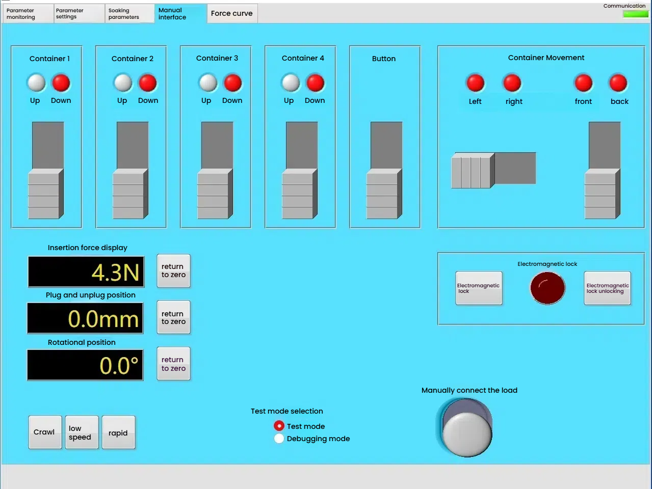
5. Enter the touch screen "Manual interface" as shown in Figure: 11
Figure 11
Manual debugging: Under the test mode selection, select "debug mode" to manually adjust
Container 1.2.3.4: Click any container to make the container rise or fall. The rising light is yellow, and the light on container 1.2.3.4 is on (red). Downward is gray, and the lights of container 1.2.3.4 are on (red)
Button: Open is yellow, press the gun head button, and close is gray
Container movement: Click left, the container moves to the left, the left indicator light is on (red), click right, the container moves to the right, and the right indicator light is on (red). Before clicking, the container moves forward, the front indicator light is on (red), after clicking, the container moves backward, and the rear indicator light is on (red)
Electromagnetic lock: The electromagnetic lock can be locked and unlocked manually
Plug-in force display: Displays the plug-in force when manual. Click "Reset to Zero", the plug-in force is 0
Plug-in position: Manually adjust the plug-in position, click "Reset to Zero" after the adjustment is completed, which is the plug-in zero point.
Rotation position: Manually adjust the rotation angle, click "Reset to Zero" after the adjustment is completed, which is the rotation zero point.
Manually connect the load: The input and output of the load can be manually adjusted.
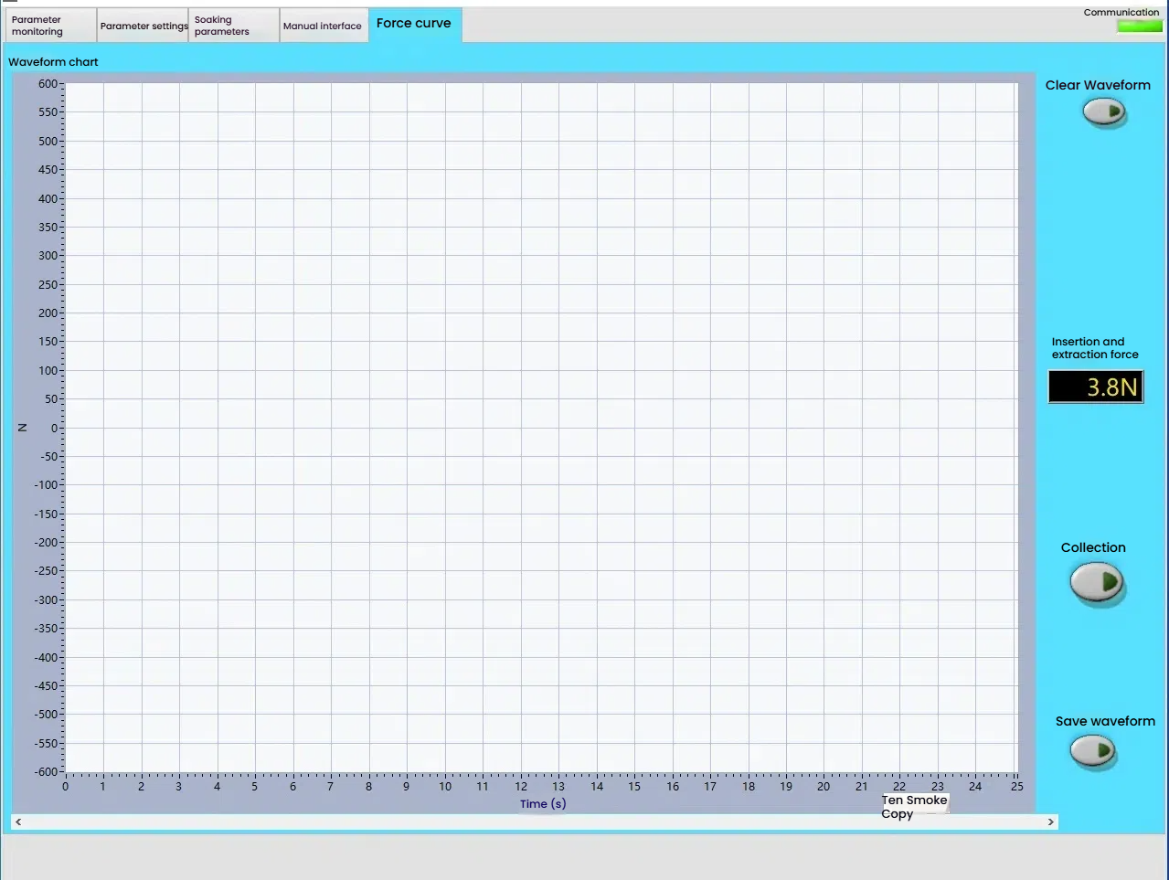
6. Enter the "Force Curve" interface on the touch screen as shown in Figure 12
Figure 12
Clear waveform: Clear the waveform collected last time
Plug-in force: Display the real-time plug-in force
Collection: Open the waveform collection, close, do not collect the waveform
Save waveform: Can save the waveform
7. Sample installation
Fix the sample gun head on the gun head bracket, as shown in Figure 3, keep the gun head horizontal and fixed. Adjust the slide handwheel to keep the gun seat mouth of the slide and the gun head mouth in the same straight line and in the appropriate position. Select manual control, click the button to release, and adjust the button cylinder bracket so that the front end of the button cylinder presses the gun head button in place. At this time, fix the cylinder bracket, fix the gun seat on the gun seat bracket, select the appropriate speed in the manual control of the software interface, press the side panel forward button, make the gun head move forward slowly, observe the gap between the gun seat mouth and the gun head, adjust the gun seat bracket X and Y axes, so that the gun head mouth is evenly aligned with the gun seat until it is inserted into the appropriate position of the gun seat, and then fix the gun seat screw. Press the side panel zero point confirmation button for 2 seconds, and the current position is zero. You can also press the "Set to Zero" button in the software interface to set the zero point, and then press the back button on the side panel to slowly back the gun head to the appropriate position. Record the distance data of the plug-in position display on the current manual control interface. Press the zero confirmation button again, and the distance of the plug-in position display on the manual control interface is 0. Write the plug-in stroke on the parameter setting interface to the data just now, and the positioning is completed.


