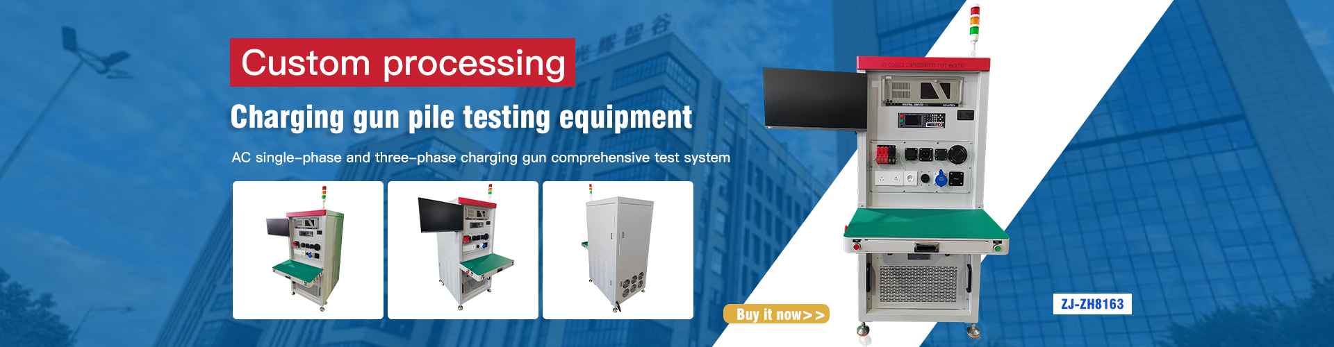
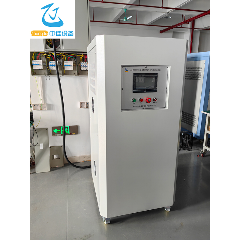
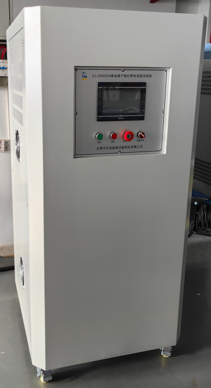
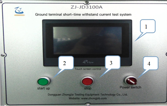
Ground Terminal Short-Time Withstand Current Test System
ZJ-JD3100A
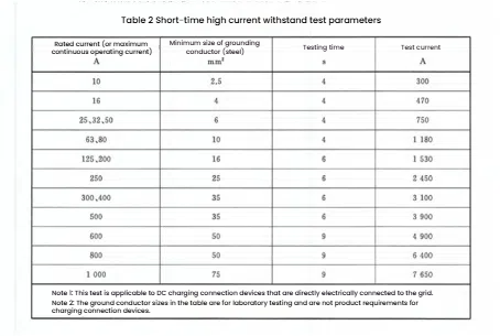
The equipment meets the test requirements of clause 7.5.2 of GB/T 20234.1-2023 and chapter 12 of IEC62196-1-2022.
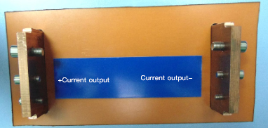
This equipment is suitable for high current load test and temperature rise test of charging connectors, couplers, switch cabinets, circuit breakers, contactors, current transformers and other electrical equipment, with casters and foot cups at the bottom.
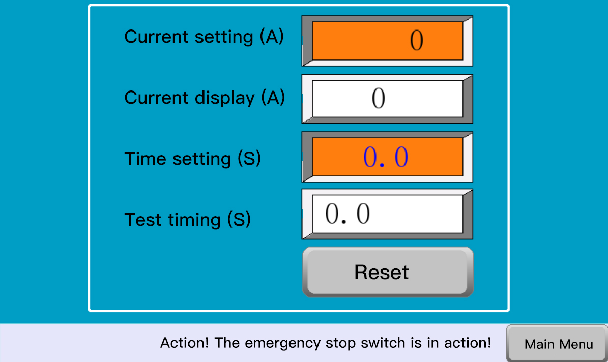
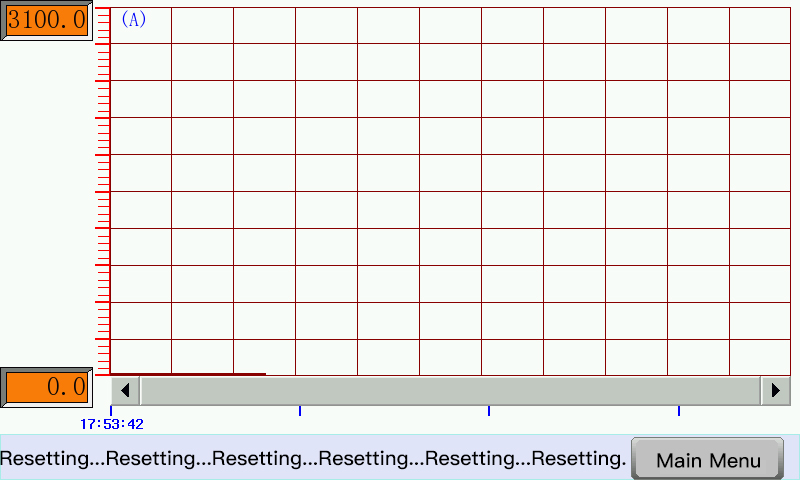
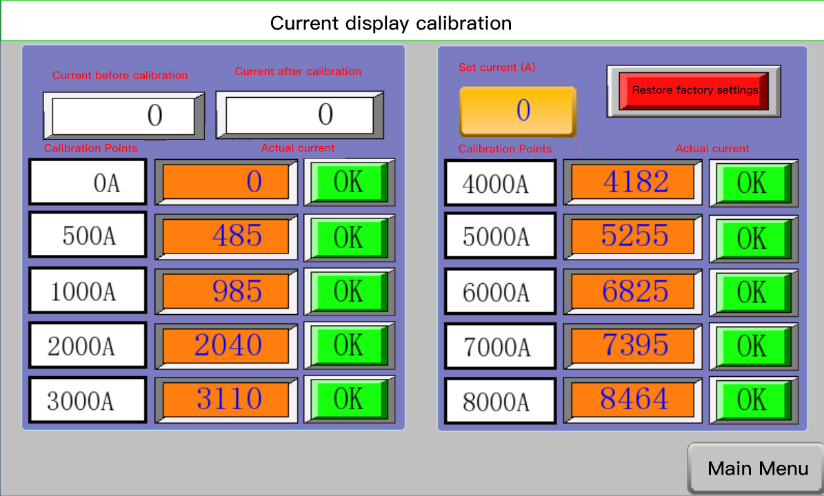
The current size is set on the touch screen, and the current automatically and stably outputs the set value of the current according to the resistance value of the sample. The current rise time is fast, which meets the requirements of short-time testing.
The equipment chassis adopts sheet metal welding, which is reliable in bearing capacity, and the panel adopts aluminum plate silk screen printing, which is beautiful and generous.