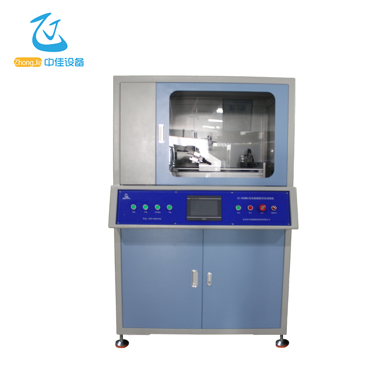
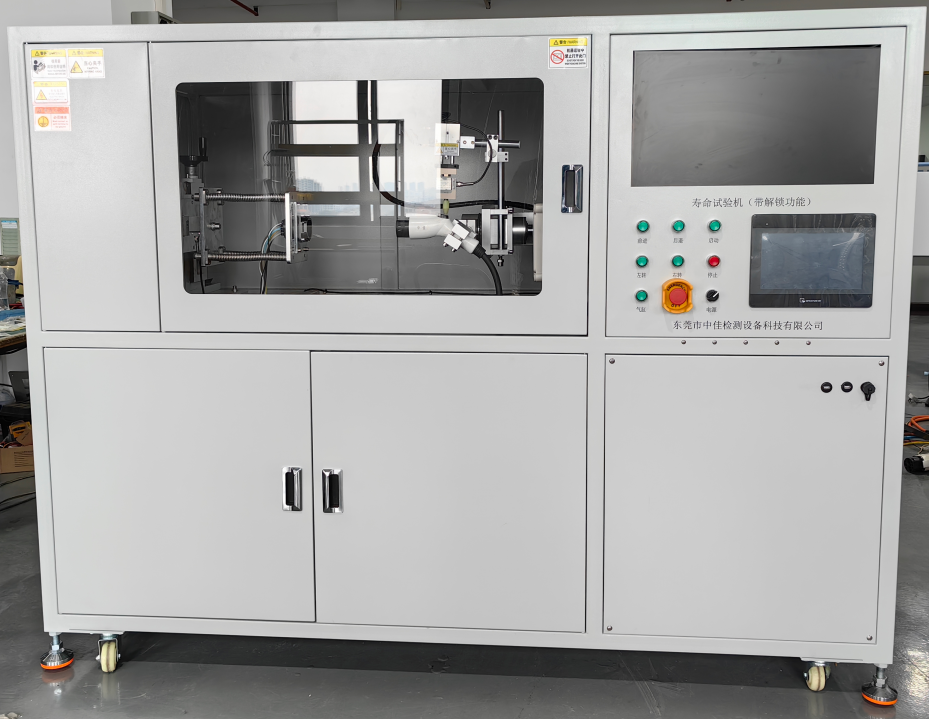
Charging Gun Plug-In Life Testing Machine
ZJ-CBSM01
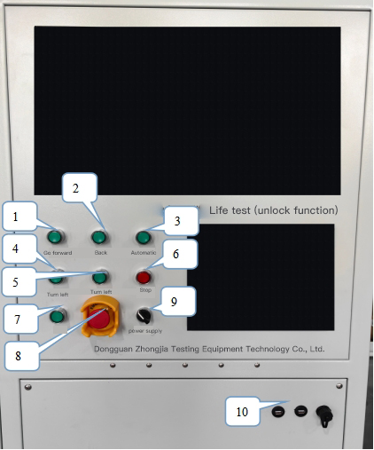
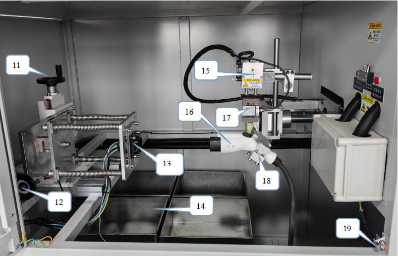
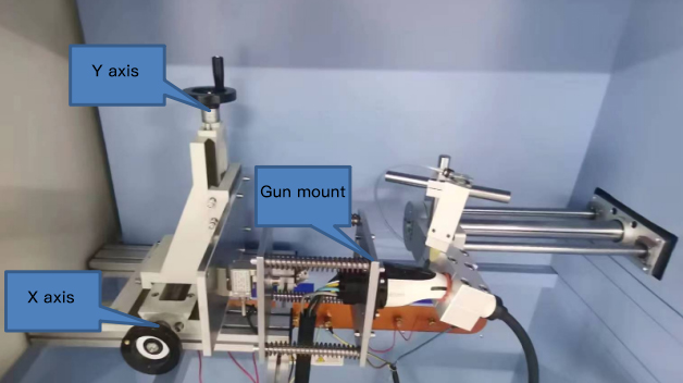
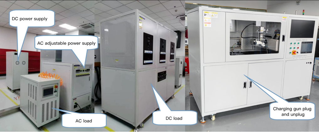
This equipment is suitable for the charging gun plug and socket breaking capacity and normal operation life test, locking device test, and plug-in force test. It uses servo electric cylinders, servo motors, air cylinders, etc. as power, and a small fixture to clamp the sample. The touch screen and programmable controller (PLC) are the control center. It has superior performance, easy operation, and a high degree of automation. It can clamp the charging gun, automatically immerse the charging gun in acid rain solution, saline solution, and muddy water solution in turn, and then automatically take it out and insert it into the charging gun holder. The last power-on is 1.5 hours, and the action is repeated to simulate the plug-in life of the charging gun outdoors. All test items meet the requirements of GB/T18187.1-2015, GB/T20234.1-2023, and GB/T11918.1-2014.