Serial number | Technical Parameters |
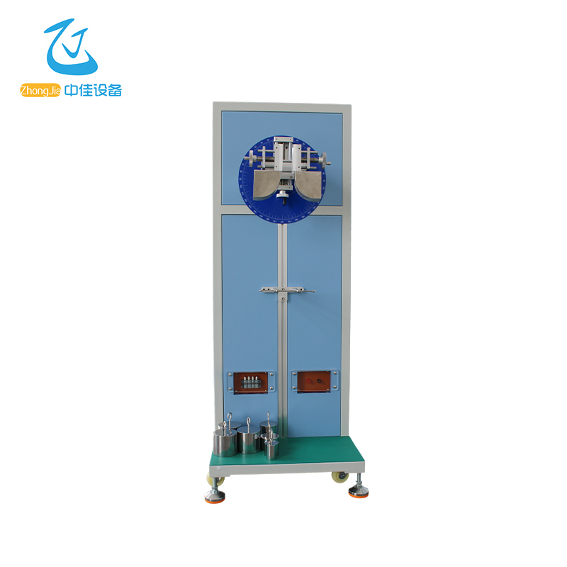
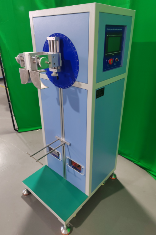
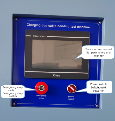
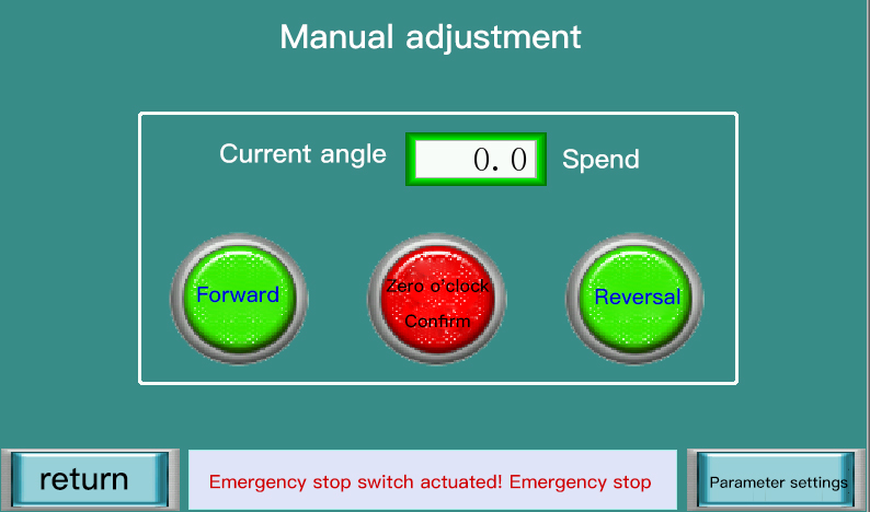
1 | Control system: imported 7-inch human-machine interface (true color LCD touch screen), Panasonic programmable controller (PLC) |
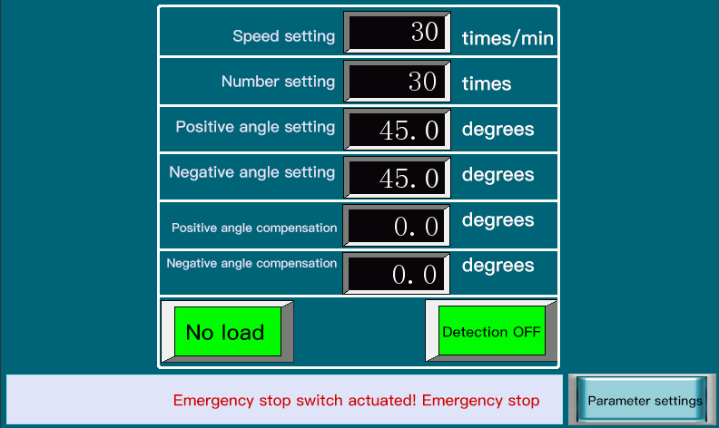
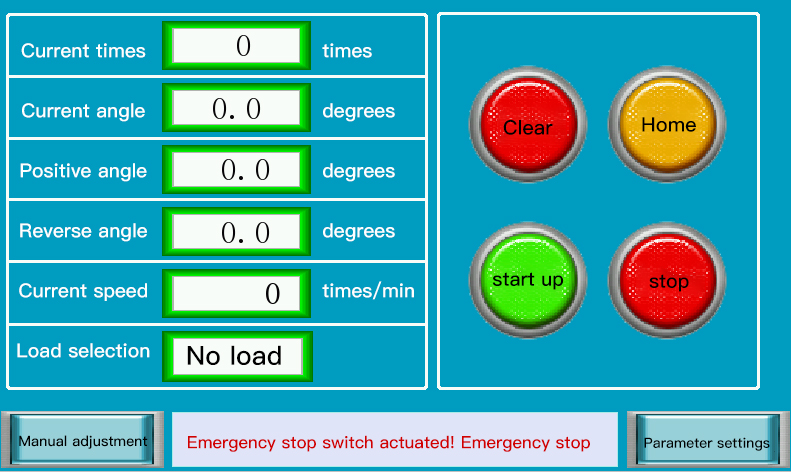
2 | Screen settings and display information: parameter monitoring, angle setting, speed pre-adjustment, count setting, alarm indication and character prompts, etc. |
3 | Test station: single station |
4 | The program can set the experiment of single station or any station by itself |
5 | Test rate: can be set and intelligently adjusted (0-80 times/minute (one round trip counts as one time) |
6 | Test bending rotation angle: can be set and intelligently adjusted (left and right angles 0~180 degrees test angle can be preset) |
7 | Total angle*speed is less than 5400 |
8 | Counter: 0 to 9999999 times can be preset, with power failure memory function |
9 | Weight: The configured weights can be combined into 20N, 25N, 50N, 75N, 100N, 120N/140N/180N; |
10 | Material A3, surface plating |
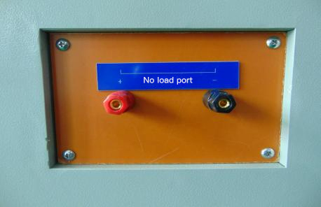
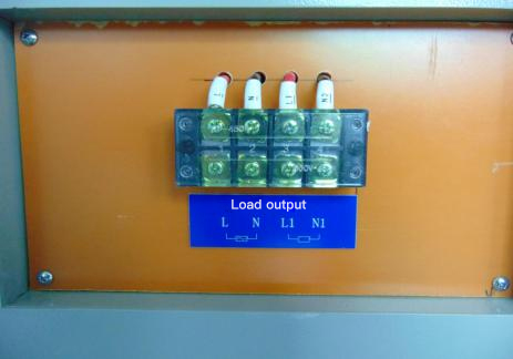
11 | Reserved load access port current ≥ 800A |
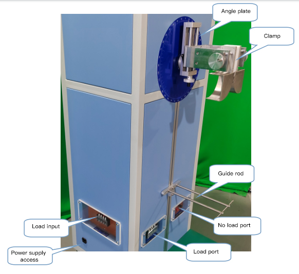
12 | External pointer displays the bending angle from 0 to 360 degrees |
13 | With disconnection detection function |
14 | Powertrain: servo motor + turbine reducer |
15 | Test cable range: diameter 5~70mm |
16 | 1 set of fixing bracket with wires for easy installation of wire clips |
17 | Dimensions: about W950*D650*H1600mm |
18 | Weight: Approx. 220Kg |
19 | Power supply voltage: AC220V±5%, 50Hz10A |
20 | The equipment meets the requirements of Figure 9 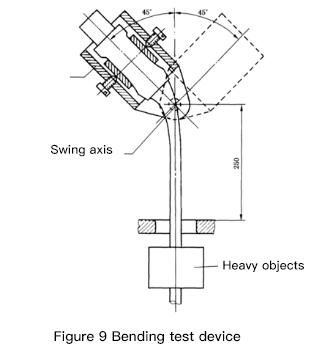
|
Serial number | Technical Parameters |
1 | The whole machine is welded by sheet metal, the surface is painted, and the panel is made of aluminum plate with sandblasting and silk screen printing. |
2 | Working power supply: three-phase AC380V 50HZ; |
3 | Equipment control mode: Panasonic PLC + touch screen control; |
4 | Tensile force: can be combined into 80N, 100N, 110N, 120N, 160N, 200N, 240N, 250N, 300N, 400N, 500N, 600N. |
5 | Torque: 0.6Nm, 0.7Nm, 1.2Nm, 1.5Nm, 2.3Nm, 11Nm, 0.35 Nm, 0.425 Nm, 0.61 Nm, 0.8 Nm, 3 Nm, 4.0 Nm, 4.5 Nm, 5.0 Nm of torque can be achieved. |
6 | Test times: 0 to 999999 times adjustable |
7 | Tensile frequency: 1 time/second |
8 | Torque time: 1min~99H99M99S |
9 | Dimensions: 1300x800x1400mm |
10 | Test data is set on the touch screen |
11 | With power-off data storage memory function |
12 | Meet the following form requirements: 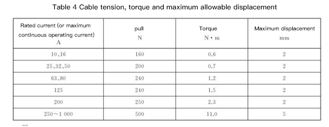
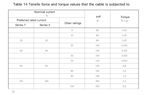
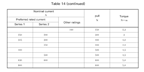
|
13 | The equipment meets the requirements of Figure 6 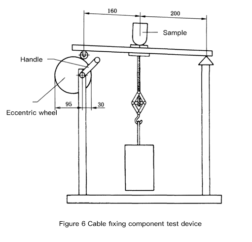
|