- Home
-
Our Services
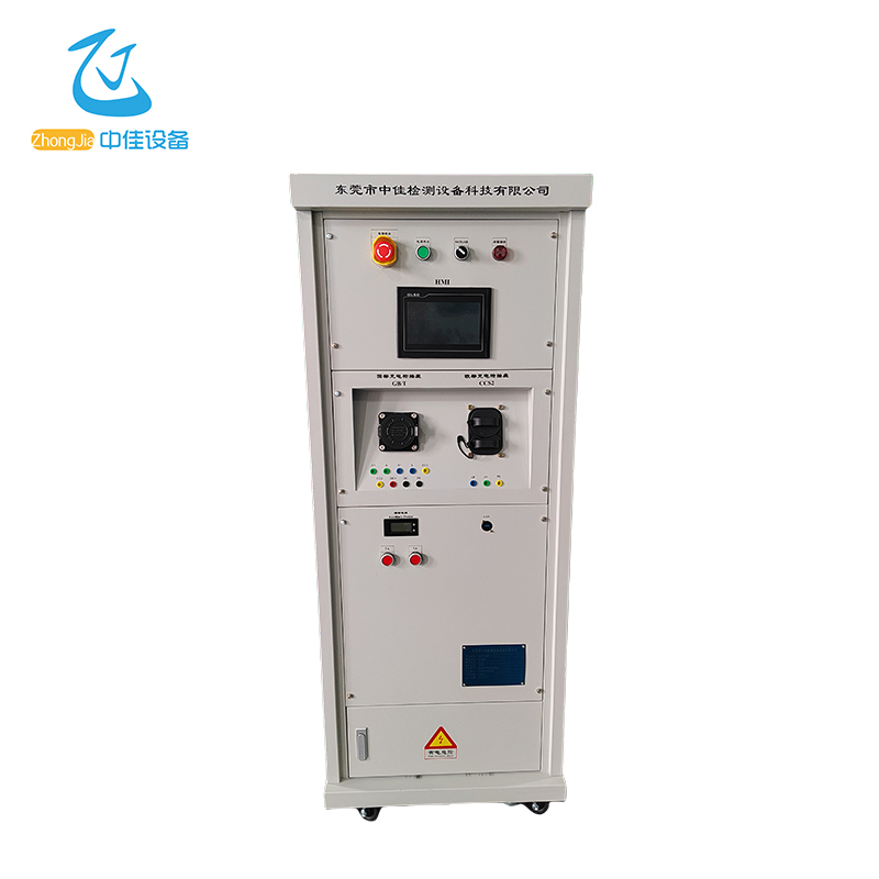
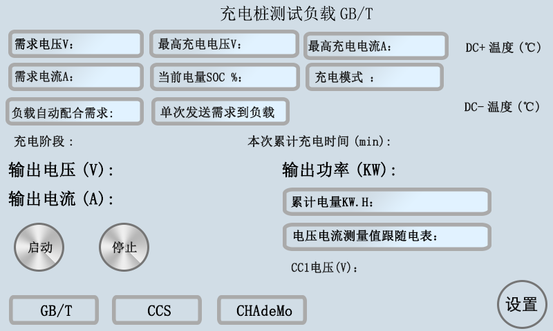
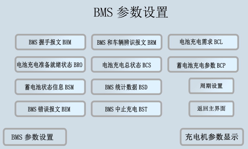
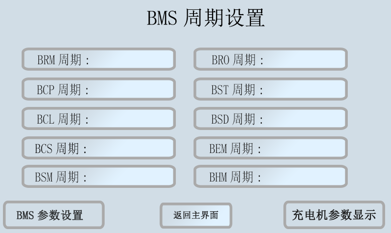
- Charging Gun Pile Testing Equipment
- Resistive Load Box
- Home Appliances And Medical Device Testing Instruments
- Connector Testing Equipment
- Inrush Current Detection Equipment
- AC Single-Phase And Three-Phase Charging Pile Testing Equipment
- Charging Gun Plug And Unplug Detection Equipment
- Vehicle Rolling Detection Equipment
- Charging Gun Seat Temperature Rise Detection Equipment
- Test Bench
- Testing Machine
- Test System
- Charging Pile Test Device
- Charging Pile Tester
- Detector
- Voltage Drop Tester
- Test Equipment
- Tester
- Load Bank
- Connector Harness Testing
- Display
- News
- About
- Contact Us
- Partners