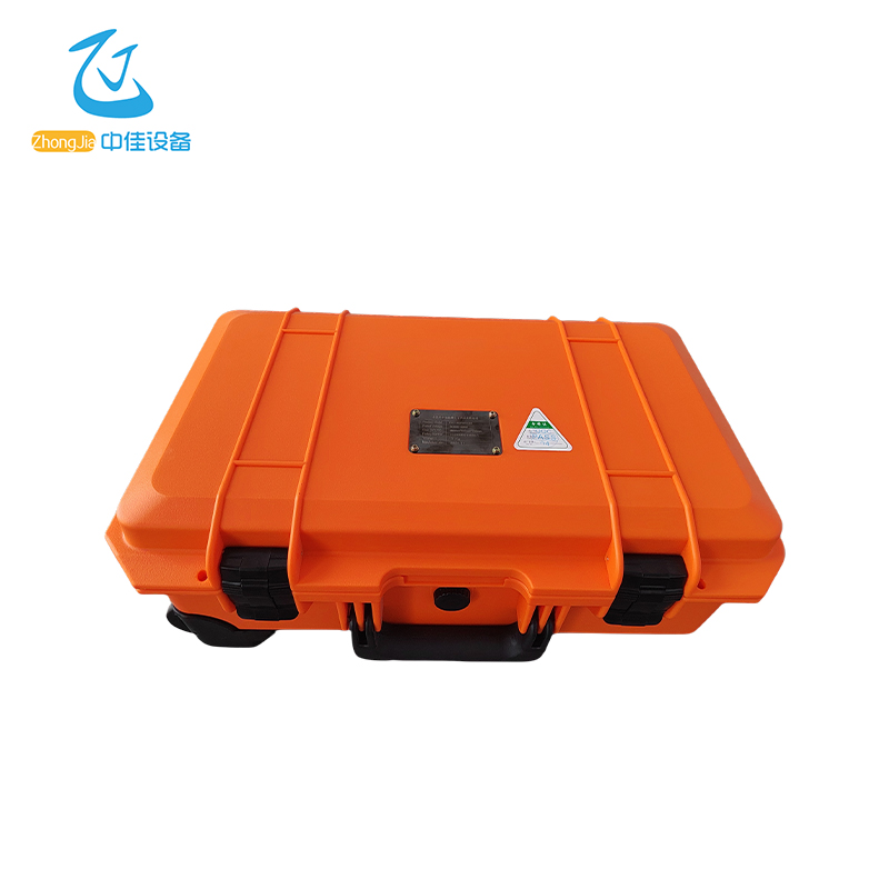
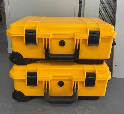
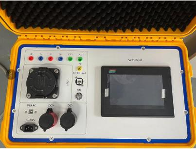
Portable Charging Pile Tester
VCD-BG01
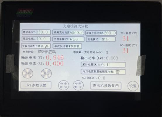
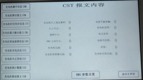
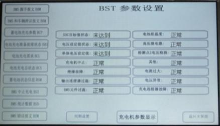
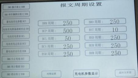
CD-BG01 complies with the national standard GB.T27930-2015 "Communication protocol between non-onboard conductive charger and battery management system of electric vehicle" and is compatible with the national standard GB.T27930-2011 communication protocol. It is suitable for DC charging pile testing, and the 7-inch touch screen operation interface is convenient and simple. The product comes with a host computer operation software to realize a variety of testing and analysis methods for charging piles. It is suitable for R&D debugging, factory testing and after-sales personnel.