Instrument . application
areas
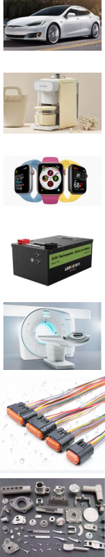 Automobile industry
Automotive wiring harnesses, headlights, engine parts, fuel tanks, water tanks, carburetors, vehicle-mounted cameras, etc.
Household appliances industry
Electric toothbrushes, dental irrigators, shavers, kettles, coffee machines, water dispensers, humidifiers,blenders, vacuum cleaners, gas stoves, electric irons, shower heads, etc.
Electronic products
Security cameras, intercoms, floodlights, smart bracelets, smart watches, smartphones,
Bluetooth headsets, Bluetooth speakers, laptops, smart locks, etc.
Battery industry
Lithium-ion battery casing, lead-acid battery casing waterproof testing, battery packs, etc.
Medical industry
Artificial dialyzers, infusion back catheters, endoscopes, syringes, infusion bags, ointment tubes,
medicine bottles, etc.
Wire connection
Wire harness connector, automotive wiring harness, lithium battery shell welding wire, communication waterproof wire, etc.
Hardware industry
Valves and pipes, die castings, stampings, radiators,
cylinders, faucets, gas joints, vacuum pumps, etc.
2 Preparation and Installation
2.1 Unpacking
When you receive our instrument, please open the package and check whether the accessories are complete and the appearance is good.
2.1.2 User preparation
a) Stable and clean compressed gas, air pressure 0.4Mpa-0.8Mpa.
b) Stable and sufficiently reliable workbench.
c) Stable and leak-free fixtures.
d) Power supply requirements AC 220V (±15%), 50HZ.
e) Plug in the instrument's power cord, air inlet pipe, test pipe, and DB15PIN connection cable for communication between the instrument and the fixture. (For detailed information on the connection method, see 3.1.4)
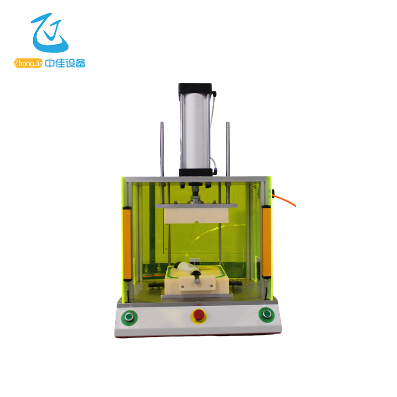
2.2 Appearance Introduction
2.2.1 Front View
2.3 Instrument Installation
2.3.1 Leak Test Equipment Operating Environment
The temperature of the test site affects the test results. Avoid direct sunlight and air conditioning as much as possible.
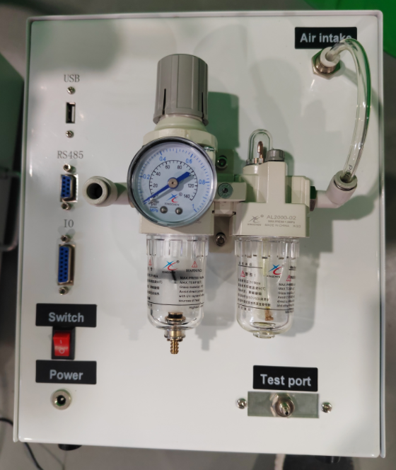
2.3.2 Connection of the air source
Note: Please make sure that the air source is turned off before connecting or removing.
2.3.3 Piping of the test port
(1) It is recommended to use a hard nylon tube that expands less when under pressure
(2) For high test pressure, choose a tube with a thick wall, and for large internal volume, choose a tube with a large inner diameter.
(3) For vacuum testing, a tube with a large inner diameter is required. For high vacuum testing, use a tube with a smooth inner wall.
(4) During the leak test, fix the tube so that it cannot move.
2.3.4 Power supply connection
(1) Please use the attached power cord. The power supply voltage range is AC 100 ~ 240 V.
(2) Please use a power supply without interference. If there is interference in the power supply circuit, use an anti-interference isolation transformer, or a transformer that can eliminate interference.
2.3.5 Signal connection
(1) IO is the input and output signal interface. (For detailed interface information, see 3.1)
(2) RS485 is the communication interface.
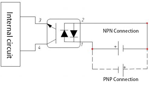
3.1.2 Input circuit
>. Photodiode input
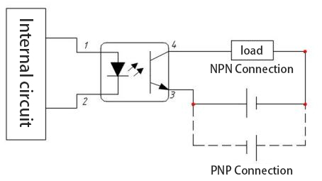
3.1.3 Output circuit
>. Open collector output
3.1.4 Connection diagram between instrument and external controller
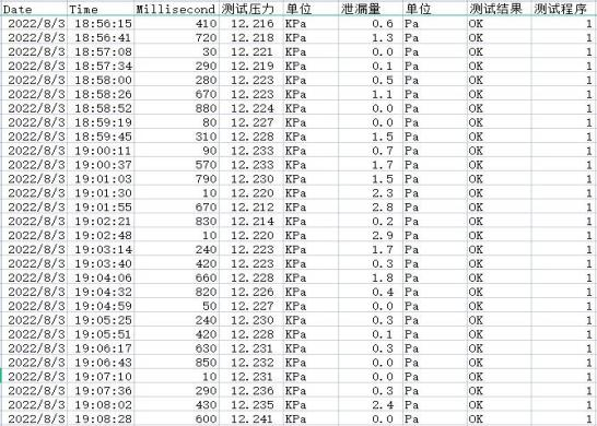
The USB interface is mainly used to export test record data. The exported file generates a folder named instrument model in the USB disk, which contains folders corresponding to the channels. The folder contains the test data of the last month in .csv format. It can be opened directly with Microsoft Excel software. The exported data is as shown in the figure below
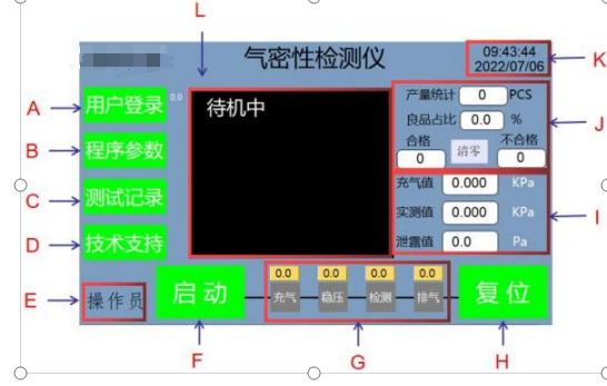
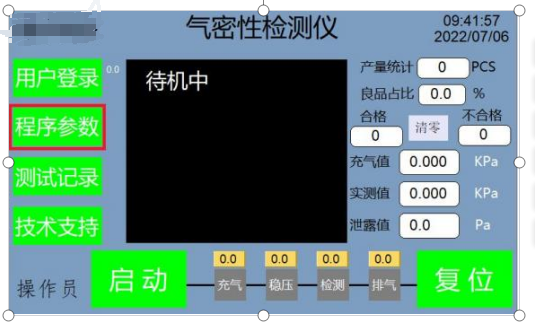
4 Instrument interface function introduction
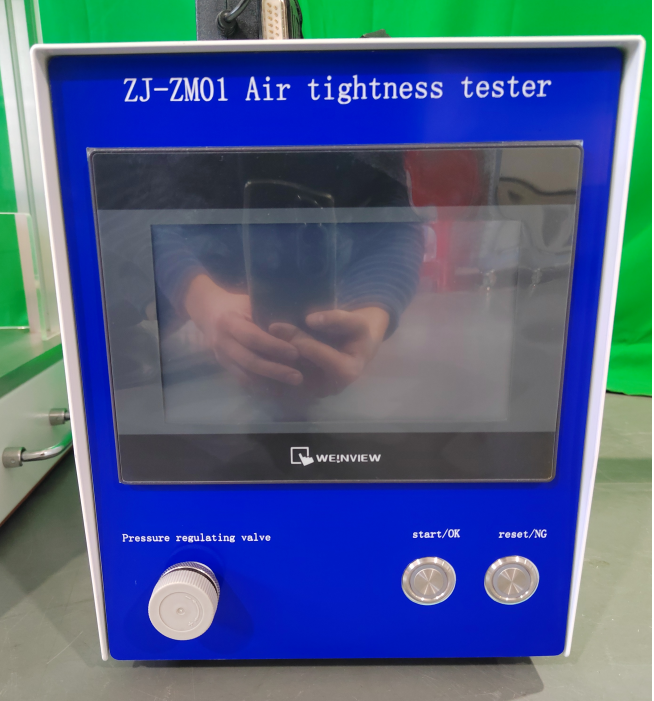
4.1 Test interface description A: User login button
B: Program parameter button
C: Test record button
D: Technical support button
E: User name status bar
F: Start test button
G: Instrument detection status
H: Reset stop button
I: Pressure value display bar at the lower right (including inflation value, measured value, leakage value)
J: Output value display bar at the upper right (including output statistics, good product ratio, qualified quantity, unqualified quantity, reset)
K: Current time and date display bar
L: Current test pressure real-time curve and test result OK or NG display box
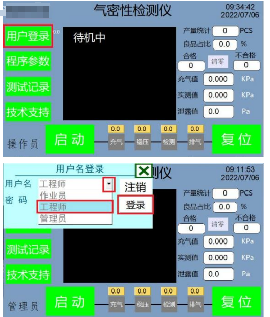
4.2 User login interface
>. Enter the user login interface In order to ensure the security of user data and prevent misoperation, when we need to set parameters, we need to log in to the parameter setting interface with a login password to modify the parameter settings. Select the user name permission, then enter the password corresponding to the user name permission, touch the button to log in, and you can enter the instrument (program parameters) settings. User name description a) Operator: can operate the instrument, but cannot modify parameters. b) Engineer: can operate the instrument, view and modify parameters, and save parameter settings. c) Administrator: has manufacturer management authority and can operate the machine, modify parameters, add and delete users. Password description a) Operator default password: 111111 b) Engineer default password: 123456
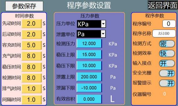
4.3 Program parameter setting interface
>. Enter the program parameter interface
A Time parameters
(1) Pre-action time: indicates the time required for solenoid valve 1 to control the cylinder to press down to seal or press the product into place. (2) Post-action time: indicates the time required for solenoid valve 2 to control the cylinder to push sideways or press down to seal the product into place. (3) Filling time: used when testing fully sealed products, the time for the quantitative air intake control instrument to fill the volume tank with air, generally 3-5 seconds.
(4) Filling time: when the detection mode is open (i.e. open product testing), the filling time indicates the time it takes for the instrument to fill the product to be tested. When the detection mode is sealed (i.e. sealed product testing), the filling time indicates the time it takes for the volume tank to fill the gap between the product and the mold, generally set to 5-10 seconds.
(5) Stabilizing pressure time: the time it takes for the gas filled into the product to stabilize the pressure, generally set to 5-10 seconds.
(6) Detection time: the time when the sensor starts to detect the change of leakage value. The longer the time is set, the greater the leakage value, it is generally set to 5-15 seconds, depending on the product.
(7) Exhaust time: set the time of the exhaust process of the product or fixture, generally set to 1-3 seconds.
(8) Interval time: the interval between the reset of solenoid valve 2 and the reset of solenoid valve 1.
B Pressure parameters
(1) Pressure unit: 6 types (Pa, KPa, bar, atm, PSi, mmHg).
(2) Leakage unit: 7 types (Pa, KPa, mbar, atm, sccm, Pa*m3/s, Pa/s).
(3) Detection pressure: set this value to be consistent with the actual detection pressure value of the product. After the program saves the record, it is convenient to know how much the actual detection pressure value of this group of programs should be adjusted to when calling the program next time.
(4) Pressure stabilization upper limit: Set the upper limit of the pressure stabilization after the inflation pressure is completed. If the inflation pressure exceeds this set value after the inflation process is completed, the product is judged as NG.
(5) Pressure stabilization lower limit: Set the lower limit of the pressure stabilization after the inflation pressure is completed. If the inflation pressure is lower than this set value after the inflation process is completed, the product is judged as NG.
(6) Leakage upper limit: Set the maximum standard value of the leakage allowed by the tested product.
(7) Leakage lower limit: Set the minimum standard value of the leakage allowed by the tested product.
(8) Effective volume: The error of this value setting will directly affect the accuracy of the test flow. The effective volume is the sum of the volume of the internal channel of the instrument, the volume of the connecting tooling pipeline and the volume of the tested workpiece.
C Program parameters
(1) Program number: used to set the number of the current product under test. Only digital naming and saving are supported.
(2) Program name: used to save the name of the current setting parameters. Only digital or alphabetical naming and saving are supported.
(3) Detection efficiency: the detection efficiency is set by the customer according to actual needs.
(4) Input contact: used to control the switch of the start, stop and other signals between the instrument and the external fixture.
(5) Safety grating: when it is off, the safety grating can be turned off and the instrument can be started directly. If the safety grating is not installed, the instrument cannot be started when this option is turned on.
(6) Alarm prompt: when there is NG product among the tested products, the instrument will sound a prompt. This prompt can be turned on or off by switching on the switch status.
After we set the parameters, they are not saved permanently. When the instrument loses power, it will restore to the original saved parameters. Only when we click (parameter save) and press and hold for more than 2S to confirm that the save is complete will it be saved permanently. You can set a model number and model name, so that we can call up the parameter information of any tested product at any time.
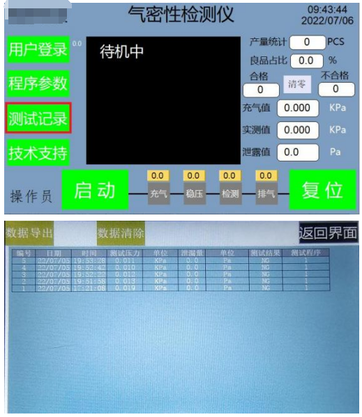
4.4 Test record interface
>. Enter the test record interface After clicking the (Test Record) button on the left menu bar to enter the test record interface, first insert the USB flash drive, then click the (Data Export) button on the test record interface to copy and export the test records to the USB flash drive. To clear the historical test records, press and hold the (Data Clear) button for more than 2 seconds to complete the data clearing action.
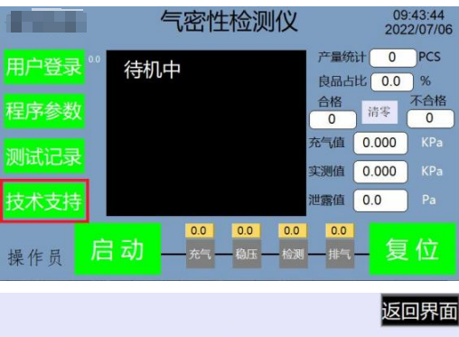
4.5 Technical support interface
>. Enter the technical support interface Click the button (Technical Support) on the left menu bar to enter the technical support interface, which contains the wiring diagram of the instrument and external controller, and basic information about the manufacturer's sales and after-sales service.
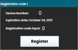
4.6 Instrument Registration
The instrument registration function is only used when the instrument is on trial. When the instrument trial expires, only by entering the correct registration code can the instrument be activated for continued normal use. When the instrument is about to expire or has expired, there will be a prompt message on the main interface. 5 Operation process
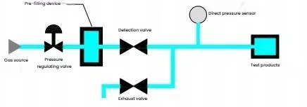
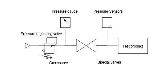
5.1 Working principle of the instrument
This instrument adopts direct pressure principle detection, which is simple to operate and easy to learn and understand.
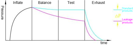
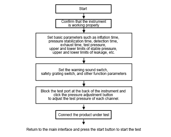
(1) Basic principle diagram: (2) Pressure change curve: 5.2 User Operation Process 6 Leak detection principle and basic knowledge of leak detection
6.1 Waterproof and dustproof grade standards
With the rapid development of electronic products, the demand for waterproof grades of daily necessities such as mobile phones, digital cameras, and tablet computers continues to increase. Waterproof IPX5-IPX8 can be achieved through airtightness testers, and achieve fast and accurate testing efficiency.6.2 Test principle of this instrument
6.2.1 Pressure drop type (direct pressure type) After applying positive or negative pressure to the test product, close the valve and measure the pressure drop caused by the leakage of the test product through a pressure gauge, pressure sensor, pressure switch, etc., to determine whether the product is leaking.
Features:
(1) It uses the direct pressure principle for detection, which is simple to operate and easy to learn and understand.
(2) Because air is used as the detection medium, there is no operating cost.
After pressurizing the standard product and the test product at the same time, close the pneumatic valves 1 and 2. If the test product is leaking, the pressure on the test product side will drop. The pressure difference between the test product and the standard product is obtained through the differential pressure sensor to determine whether the test product is leaking.
(1) Both the test product and the standard product will cause pressure changes due to temperature and deformation of the test product. The differential pressure test method can offset the impact of this change.
(2) Because air is used as the detection medium, there is no operating cost.
The basic principle of flow test is: fill the test workpiece with gas of specified pressure, maintain a certain pressure in the workpiece through the pressure reducing valve, and the instrument measures the current gas flow.
Features:
(1) The flow rate generated by the leak remains very stable over time.
(2) Because air is used as the detection medium, there is no operating cost.
6.3 Basic knowledge of leak detection
Currently, there are two main detection methods for airtightness detectors: differential pressure and direct pressure. Since the detection of small pressures will be affected by many factors such as temperature and air pressure, the detection results of the leakage amount will also be affected.
Factors affecting leakage results
The leakage amount is calculated by the pressure drop of the closed cavity and the cavity volume. The size of the pressure drop is closely related to the detection pressure and detection time. Changes in any parameter will directly affect the detection results.
6.3.1 Detection pressure
Whether the leakage amount of the workpiece is qualified should be judged under the detection pressure conditions given by the corresponding standards. For leaks of the same size, when the detection pressure changes, the pressure drop caused in the same time will change.
Similarly, for the workpiece with small leaks, the leakage amount will be different under different detection pressures.
6.3.2 Detection time
The detection process of the leak detector is divided into four steps: filling, stabilizing pressure, testing and exhausting. Each step requires time setting. The gas needs to reach a stable state before the leakage detection can be carried out. Under ideal conditions, the longer the detection time, the higher the detection accuracy of the leakage. However, in use, a reasonable time range should be determined according to the actual situation to ensure efficiency.
6.3.3 Detection interval time
According to the ideal state gas equation:
PV = nRT
Where: P—the pressure of the ideal gas, V—the volume of the ideal gas, n—the amount of gas substance, T—the thermodynamic temperature of the ideal gas. It can be seen that the pressure of the gas is related to the volume and temperature. During the leak detector detection process, the gas is compressed in the closed cavity, which will cause the gas temperature to rise. The temperature change has a greater impact on the detection of small pressures, which will eventually affect the detection results of the leakage. Therefore, when using the leak detector for the second detection, it is necessary to wait for the differential pressure sensor and the gas in the gas path to return to the original temperature and deformation state. Since it is difficult to directly detect the gas temperature in the cavity, the interval between two tests can be increased to ensure that the gas
restores to the original temperature.
6.4 Volume of the cavity of the workpiece being tested
During the test, the gas leakage of the workpiece being tested is calculated by the pressure drop of its internal cavity and the cavity volume:
ΔV = P root VΔP
Where: ΔV— calculated value of volume change. V—the sealing volume of the object being tested by the leak detector and the volume of the connecting gas path. P0—atmospheric pressure. P—test pressure. ΔP—measured value of the pressure drop of the leak detector.
It can be seen that when the test pressure and pressure drop are the same, the cavity volume of the workpiece being tested is proportional to the leakage,
so the accuracy of the measured cavity volume measurement will affect the size of the leakage.
6.5 Parameter Capture Method
(1) Test pressure: Determine the test pressure according to the working conditions of the workpiece.
(2) Inflation time: a. The inflation time should be greater than 2 seconds, b. The larger the product volume, the longer the inflation time, otherwise, the shorter it is. c. The smaller the rigidity (softer) of the product, the longer the inflation time, otherwise, the shorter it is. d. The larger the test pressure, the longer the inflation time, otherwise, the shorter it is. First set the inflation time in the parameter to a longer time, such as a few minutes. Then exit to the main interface, put the workpiece to be tested in the fixture, and then press the start button. At this time, observe the pressure curve on the instrument. When the pressure curve reaches a flat state, the inflation time value displayed by the instrument is set as the inflation time. (That is, the time required for the pressure curve to climb from 0 to the inflation pressure)
(3) Balance time: The principle is equal to or approximately less than the inflation time.
(4) Detection time: a. The detection time must be at least more than 3 seconds, b. The maximum leakage of qualified products must be less than the minimum leakage of unqualified products, less than 100pa. c. The larger the product volume, the longer the inflation time, otherwise, the shorter. d. The greater the detection pressure, the longer the inflation time, otherwise, the shorter. Grabbing method: Use water to find 3 qualified products and 3 slightly leaking products, put the 3 qualified products on the instrument for detection, repeat the detection five times for each product (the more the better), and record the maximum leakage value. Then put the 3 unqualified products on the instrument for detection, repeat the detection five times for each product (the more the better), and record the minimum leakage value. If the minimum value of the unqualified product minus the maximum value of the qualified product is less than 100pa, extend the detection time, otherwise, shorten the detection time. (5) Exhaust time: The exhaust time is related to the volume of the workpiece test chamber. The larger the volume, the longer the exhaust time. The exhaust time can be seen from the test curve. The time required from the full gas state to the zero pressure state is the exhaust time. (That is, the time required for the pressure curve to reach the zero pressure state from the test pressure state) (6) Leakage: After setting the detection time, take the middle number between the value with the smallest leakage in the extreme leakage workpiece and the largest reading value among all the test times of the OK workpiece as the leakage. For example, if the smallest leakage of the extreme leakage workpiece is 200Pa and the largest leakage of the OK workpiece is 100Pa, then the leakage can be set to 150Pa.
Troubleshooting
7.1 OK product is judged as NG
Method: Block the air pipes connecting the standard product and the test product at the back of the instrument, and then press the start button to start the test. Check the leakage to determine whether the instrument has a problem. If there is no leakage, it is not a problem with the instrument. Then you can check the fixture to see if the leakage is caused by the fixture being loose or not clamped.
7.2 The instrument cannot be started
First, confirm whether the fixture grating is correctly connected to the instrument. If the grating is not required, you need to check the "Close safety grating" in the function setting interface.
7.3 The fixture cylinder does not move, or the instrument has not entered the inflation process after the action.
If the cylinder does not move, you need to confirm whether the connection line between the instrument and the fixture is connected, and whether the cylinder air pipe is connected normally. The cylinder
does not enter the inflation process after the action may be because the instrument contact does not sense the signal, so you do not need to check the corresponding check box for the sense signal.