products
HomeOur ServicesVoltage Drop Tester

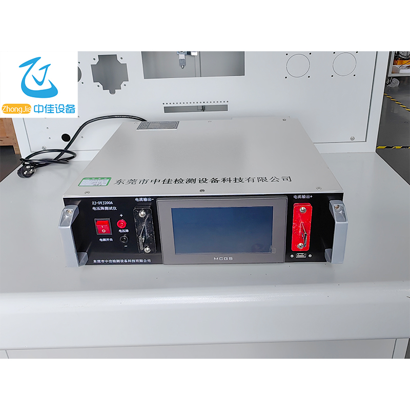
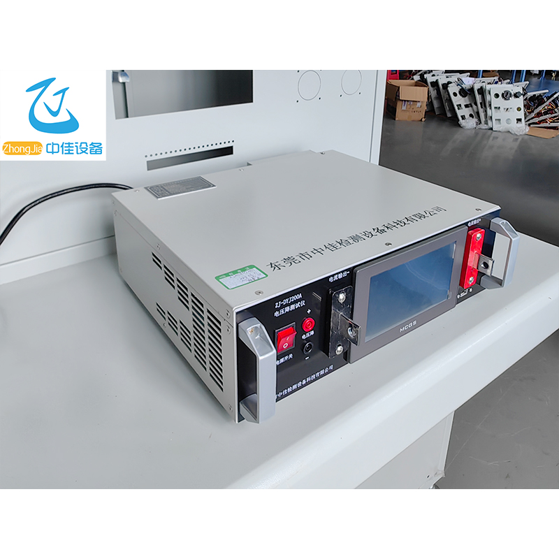
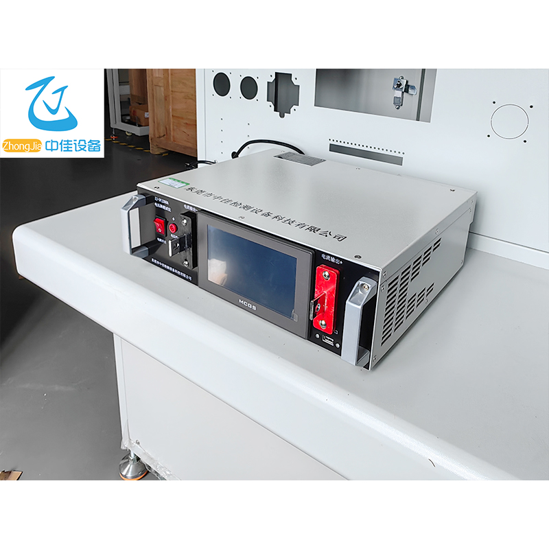
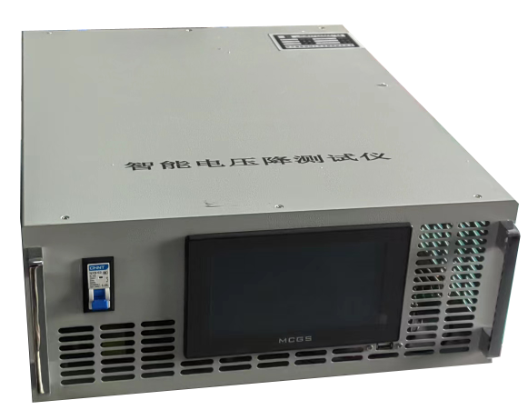
Voltage Drop Tester

ZJ-DYJ200A

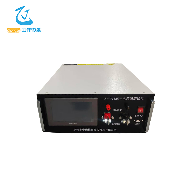
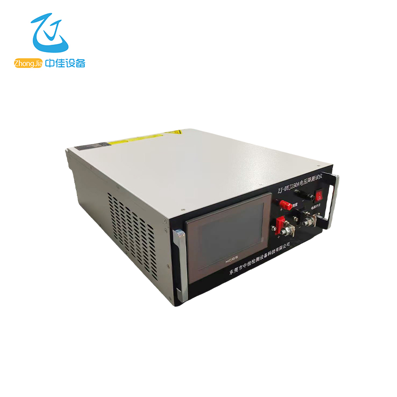
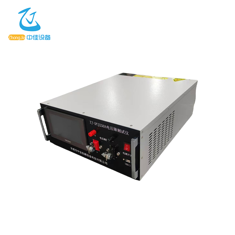
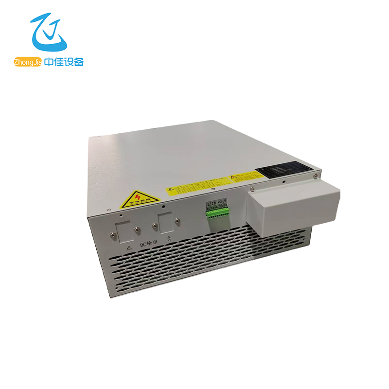
Machine picture
1. Use and maintenance
1. The use environment and storage method have a certain impact on the service life and reliability of this product. Please do not use it in the following working environment:
A. Exceeding the technical indicators.
B. High, low temperature and humid environment (temperature -25℃~+75℃, relative humidity 20%~90%).
C. Places with vibration and easy collision.
D. Places with metallic dust, corrosive substances, salt and flammable gas.
2. If it is not used for a long time, please store this power supply in a dry environment, the storage temperature range is: -25℃~+75℃. Before turning on the power supply, the ambient temperature must be warmed up to above 0℃ and maintained for more than 2 hours.
2. Performance characteristics
☆Specifications: output voltage 0-rated voltage, output current 0-rated current
☆Voltage and current preset: The panel comes with preset buttons, which can preset voltage and current values
☆Voltage and current stabilization: The voltage and current values are continuously adjustable from zero to rated values, and the voltage and current stabilization are automatically converted
☆Overvoltage protection: The machine is self-locking after protection, and the machine is automatically unlocked after restarting
☆Overcurrent protection: rated current output overload protection, short circuit protection (output is turned off after short circuit, optional)
☆Short circuit protection: Long-term short circuit or short circuit startup is allowed in any state
☆Short circuit alarm: When the output is short-circuited, the power supply will sound and light alarm
☆Output display: The voltage and current meters are all LCD displays
☆Pulse operation: It can be equipped with a time controller to form a DC pulse power supply (optional)
☆Intelligent: It can be connected to a computer via RS232 or RS485 or CAN to form an intelligent power supply monitored by a computer (optional)
☆Analog signal connection: Users can use 0 ~ 5V, 0 ~ 10V or 4 ~ 20mA signal controls and reads back the voltage and current of the power supply output (optional)
☆Special customization: Provide special specification power supply size design, special power supply customization (pre-declaration) .
3. Main technical indicators
1. Maximum output voltage: close to 0V-rated value
2. Maximum output current: close to 0A-rated value
3. Constant voltage value continuously adjustable range: 0V-rated value
4. Constant current value continuously adjustable range: 0A-rated value
5. Output voltage, output current and overvoltage setting: touch screen
6. Automatic switching of voltage and current stabilization state
7. Voltage stabilization accuracy:
Source effect ≤0.5% rated value (output voltage change rate caused by input power supply voltage change ±10%)
Load effect ≤0.5% (output voltage change rate caused by power supply output current change from zero to rated value) Output voltage change rate)
8. Current stabilization accuracy:
Source effect ≤0.5% rated value (output voltage change rate caused by input power supply voltage change ±10%)
Load effect ≤0.5% (output current change rate caused by output voltage change from zero to rated value)
9. Output ripple: ≤0.5% rated value when stabilizing voltage (effective value, measured at rated output)
10. Protection circuit: output short circuit, overvoltage, overload protection, overtemperature protection
11. Display mode: LCD screen display
12. Display resolution: determined by specification model
13. Display error: ≤1% ±1 word (within 20%-100% range)
14. Program control (optional function): The power supply provides RS485 interface and communication protocol, which is connected to the computer to form an intelligent power supply. the power supply starts, stops, sets given values, and reads voltage, current values, working status and other functions in real time through the 485 interface.
15. Working mode: long-term continuous operation at full load
16. Time drift: ≤0.5% rated value (output voltage change rate caused by continuous operation of the power supply for more than 8 hours)
17. Temperature drift: ≤0.05% rated value/°C (output voltage change rate caused by ambient temperature change within the ambient temperature range of the power supply)
18. Input voltage: single-phase 220V±10% / three-phase 380V±10%
19. Frequency: 50Hz/60Hz
20. Insulation resistance: ≥20MΩ
21. Withstand voltage: AC1500V 60S
22. Use environment: indoor
4: Touch screen operation instructions
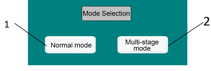
1: Touch screen startup interface instructions
1. Normal mode selection, click to enter the normal mode interface, see the following description for details.
2. Multi-stage mode selection, click to enter the multi-stage mode interface, see the following description for details.
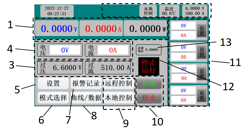
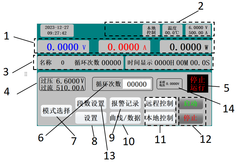
2: Normal mode interface
1: Operation parameter display 1: Displays the voltage, current, power and other parameters of the voltage during operation.
2: Operation parameter display 2: Displays the time, control mode, temperature, rated voltage, rated current and other parameters during operation.
3: Operation parameter display 3: Displays the overvoltage protection setting, overcurrent protection setting and other parameters during operation.
4: Operation parameter setting 1: Set the voltage and current when the power supply is running.
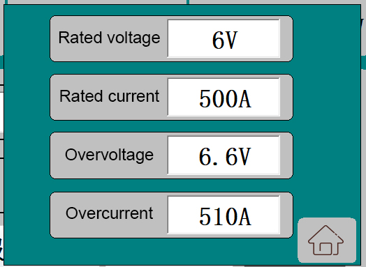
5: Operation parameter setting 2: Click to pop up the setting interface, set the rated voltage, rated current, overvoltage protection, overcurrent protection and other parameters of the power supply, the specific interface is as follows:
6: Mode selection: Click to return to the startup interface.
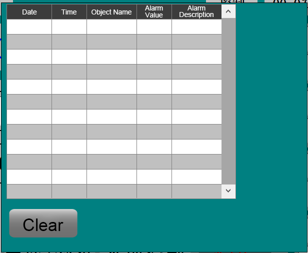
7: Alarm record: Click to pop up the historical alarm record interface, as shown in the figure:
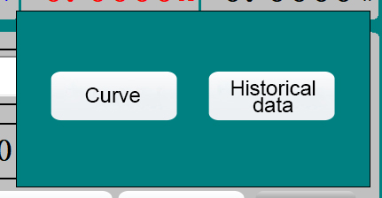
8: Operation data record: Click and the following selection interface will pop up:
Click the corresponding button to enter the operation curve interface or historical data interface, see the following description for details.
9: Control mode switch: switch the power control mode (local control/remote control).
10: Start/stop button: control the start and stop of the power supply.
11: Quick setting bar: up to 4 groups of quick settings can be made. Enter the voltage and current in the setting bar, click the corresponding setting button, and the voltage and current of the power supply can be changed to the corresponding value.
12: Operation status bar: displays the current operation status of the power supply, such as:
13: Voltage drop collection and display: Display the voltage value collected at the sampling point.
3: Multi-stage setting interface
1: Operation parameter display 1: Displays the voltage, current, power and other parameters during operation.
2: Operation parameter display 2: Displays the time, control mode, temperature, rated voltage, rated current and other parameters during operation.
3: Operation parameter display 3: Displays the operation time and current operation status in multi-stage operation mode.
4: Operation parameter display 4: Displays the overvoltage protection setting, overcurrent protection setting and other parameters during operation.ation.5: Operation status bar: Displays the current operation status of the power supply, such as:
6: Cycle times setting: set the number of cycles for multiple sections.
7: Mode selection: click to return to the startup interface.
8: Multi-section setting 3: click to pop up the setting interface, set the rated voltage, rated current, overvoltage protection, overcurrent protection and other parameters of the power supply.
9: Alarm record: click to pop up the historical alarm record interface:.
10: Operation data record: click to pop up the following selection interface:, click the corresponding button to enter the operation curve interface or historical data interface, see the following description for details.
11: Control mode switching: switch the power supply control mode (local control/remote control).
12: Start and stop button: control the power supply to start and stop.
13: Multi-section setting: set the parameters of each section of multi-section operation.
14: Voltage drop acquisition display: display the voltage value collected at the sampling point.
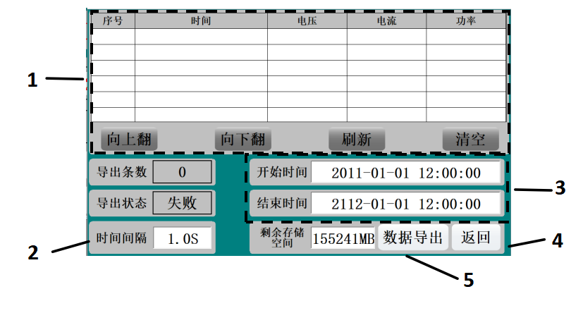
4: Data recording interface
1: Save data display: Display the saved historical data.
2: Save interval setting: Set the save period of historical data.
3: Export time setting: Set the time range of exported data.
4: Exit the data recording interface.
5: Export data to a USB flash drive.
5 Rear wiring instructions
Pin 1 RS485 A. Pin 2 RS485 B. Pin 9 External voltage sampling positive pole. Pin 10 External voltage sampling negative pole.
3.11. Communication information transmission process:
3.2When the communication command is sent from the sending device (host) to the receiving device (slave), the slave that meets the corresponding address code receives the communication command and reads the information according to the function code and related requirements. If the CRC check is correct, the corresponding task is executed, and then the execution result (data) is returned to the host. The returned information includes the address code, function code, data after execution, and CRC check code. If the CRC check is wrong, no information is returned.
3.31.1 Address code:
3.4The address code is the first byte (8 bits) of each communication information frame, from 1 to 250. This byte indicates that the slave with the address set by the user will receive the information sent by the host. Each slave must have a unique address code, and only slaves that meet the address code can respond to the return information. When the slave returns information, the return data starts with its own address code. The address code sent by the host indicates the address of the slave to be sent, and the address code returned by the slave indicates the address of the returned slave. The corresponding address code indicates where the information comes from.
3.51.2 Function code:
3.6It is the second byte transmitted in each communication information frame. The function codes that can be defined in the ModBus communication protocol are 1 to 127. As a host request, the function code tells the slave what action to perform. As a slave response, the function code returned by the slave is the same as the function code sent from the host, and indicates that the slave has responded to the host and has performed related operations.
1.3 Data area:
The data area includes what information needs to be returned by the slave or what action needs to be performed. This information can be data (such as: switch input/output, analog input/output, register, etc.), reference address, etc. For example, the host tells the slave to return the value of the register (including the starting address of the register to be read and the length of the register to be read) through function code 03, and the returned data includes the data length and data content of the register. For different slaves, the address and data information are different (a communication information table should be given).
The power supply adopts the Modbus communication protocol. The host (PLC, RTU, PC, DCS, etc.) can read its data register arbitrarily using the communication command (function code 03) (the data information table is detailed in the appendix).
The response command format is the slave address, function code, data area and CRC code. The data in the data area are all two bytes, and the high bit is in front.
4. Static time requirements
Before sending data, the data bus static time, that is, the time when no data is sent, is required to be greater than (5ms when the baud rate is 9600).
1. Power supply Modbus-RTU communication protocol
2. Serial port format

Communication rate:

9600

Data bits:

8

Stop position:

1

Check bit:

None


3. Modbus register definition

Order

Register Address

rw

illustrate

03

0002H

r

Power supply temperature low 16 bits (floating point)

03

0003H

r

Power supply temperature high 16 bits (floating point)

03

0004H

r

Power supply Actual voltage lower 16 bits (floating point number)

03

0005H

r

The actual voltage of the power supply is higher 16 bits (floating point number)

03

0006H

r

The lower 16 bits of the actual power current (floating point number)

03

0007H

r

The actual current of the power supply is higher 16 bits (floating point number)

03

0008H

r

Spare

03/06/16

0009H

rw

Power control bit (see 1.3 below for description)

03/16

000AH

rw

Power supply setting voltage lower 16 bits (floating point)

03/16

000BH

rw

Power supply setting voltage high 16 bits (floating point number)

03/16

000CH

rw

Power supply setting current lower 16 bits (floating point number)

03/16

000DH

rw

Power supply setting current high 16 bits (floating point number)

03

0020H

rw

Sampling voltage lower 16 bits (floating point)

03

0021H

rw

Sampling voltage high 16 bits (floating point)


Type and format of communication data:
Information is transmitted asynchronously and in bytes. The communication information transmitted between the master and slave is in 10-bit word format:

Word format (serial data)

10-bit binary

Start bit

1st

Data bits

8-bit

Parity bit

None

Stop bits

1st


●Communication data (information frame) format

Data Format

Address code

Function code

Data Area

CRC Check

Data length

1 byte

1 byte

N bytes

16-bit CRC code (redundant cyclic code)


●Communication data (information frame) format

Function code

Definition

Operation (binary)

02

Read switch input DI

Read one or more switch status inputs (remote signaling)

01

Read status output OUT

Read one or more switch output status data

03

Read register data

Read data from one or more registers

05

Write switch output OUT

Control one relay "close/open" output, remote control

06

Write single register

Write a set of binary data to a single register

10

Write multiplexer register

Write multiple sets of binary data into multiple registers

×

Contact Us

captcha