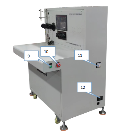
⑫ Machine nameplate informationInstructions for use
1. Connect the power cord to the AC220V power supply and press the power switch.
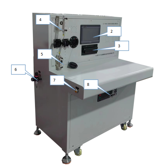
2. Electrical connection The filter on the left side of the equipment is connected to the external 0.6MPA gas source, the power input on the right side of the equipment is connected to the external power supply AC220V 50HZ, and the main power switch of the leakage switch on the right side is turned on.
3. Sample installation Select a suitable sample socket and install the sample on the equipment. For example: AC single-gun head single-phase line. Connect the sample head to the AC socket at the top of the equipment head, and the sample tail to the tail terminal at the tail of the equipment.
4. The initial interface displays the company name, and automatically enters the "Main Menu" screen after displaying for 3 seconds:

Figure (4)5. Enter the "Main Menu" interface:
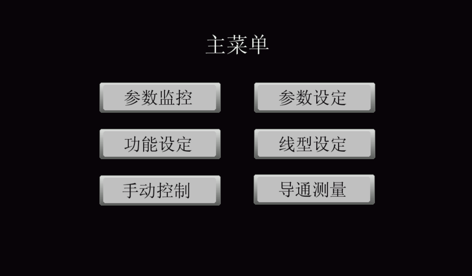
Figure (5)6. Enter the level password 1618:
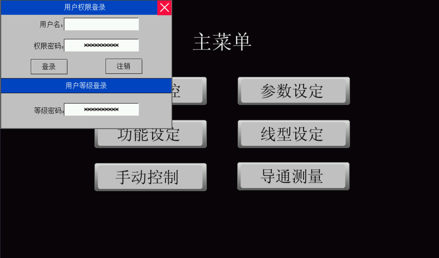
Figure (6)7. Enter the main menu "Parameter Monitoring" interface:
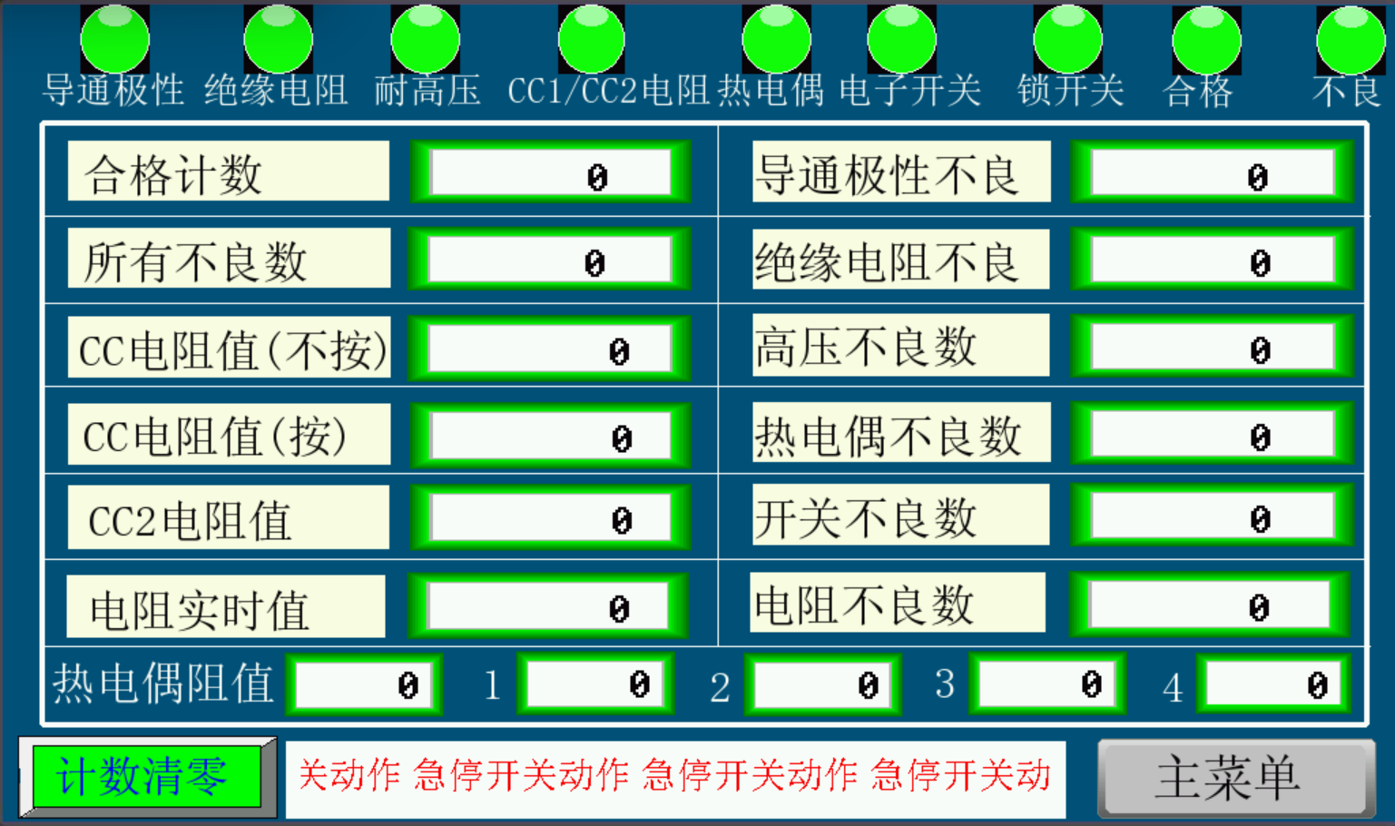
Figure (7)
Figure (8)
High-pressure test machine: After turning on the power, press the button on the right side of the standard mode to enter the standard mode. After entering the main menu, set the corresponding parameters.
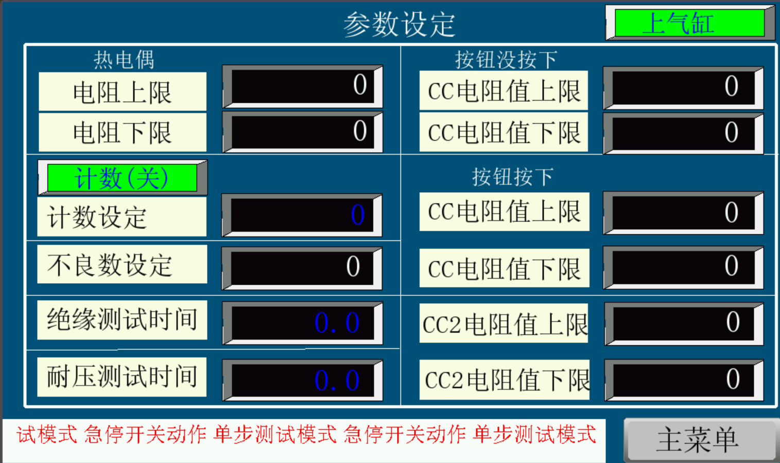
8. Enter the main menu "Parameter Setting" interface:
Figure (9)
Parameter setting: set the count, number of defects, upper and lower limits of thermocouple resistance, withstand voltage test time, insulation test time, upper and lower limits of CC/CC2 resistance value and other parameters.
Press the panel "Start" button, the equipment starts to run with the set parameters: conduction test > thermocouple test, withstand voltage test > CC/CC2 test > test completed. If any step alarms, the equipment stops working. The alarm reason can be observed in the alarm information column.
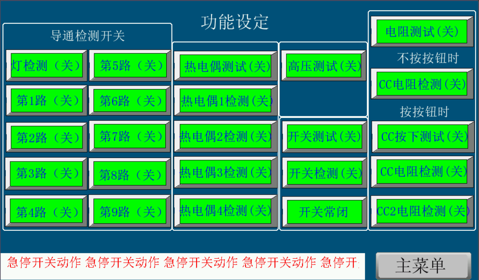
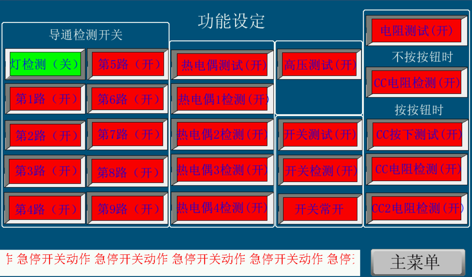
9. Enter the main menu "Function Setting" interface:
Figure (10)
Figure (11)
Function setting: according to the test performance, turn on the left conduction switch, thermocouple test switch and thermocouple detection switch, resistance test switch and CC/CC1 press or not press resistance detection switch. Switch test, high voltage test and other switches.
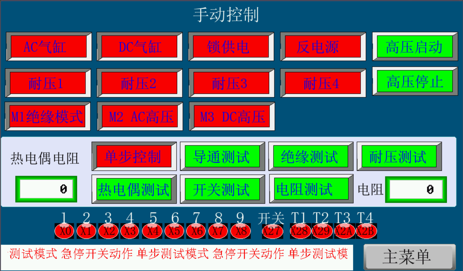
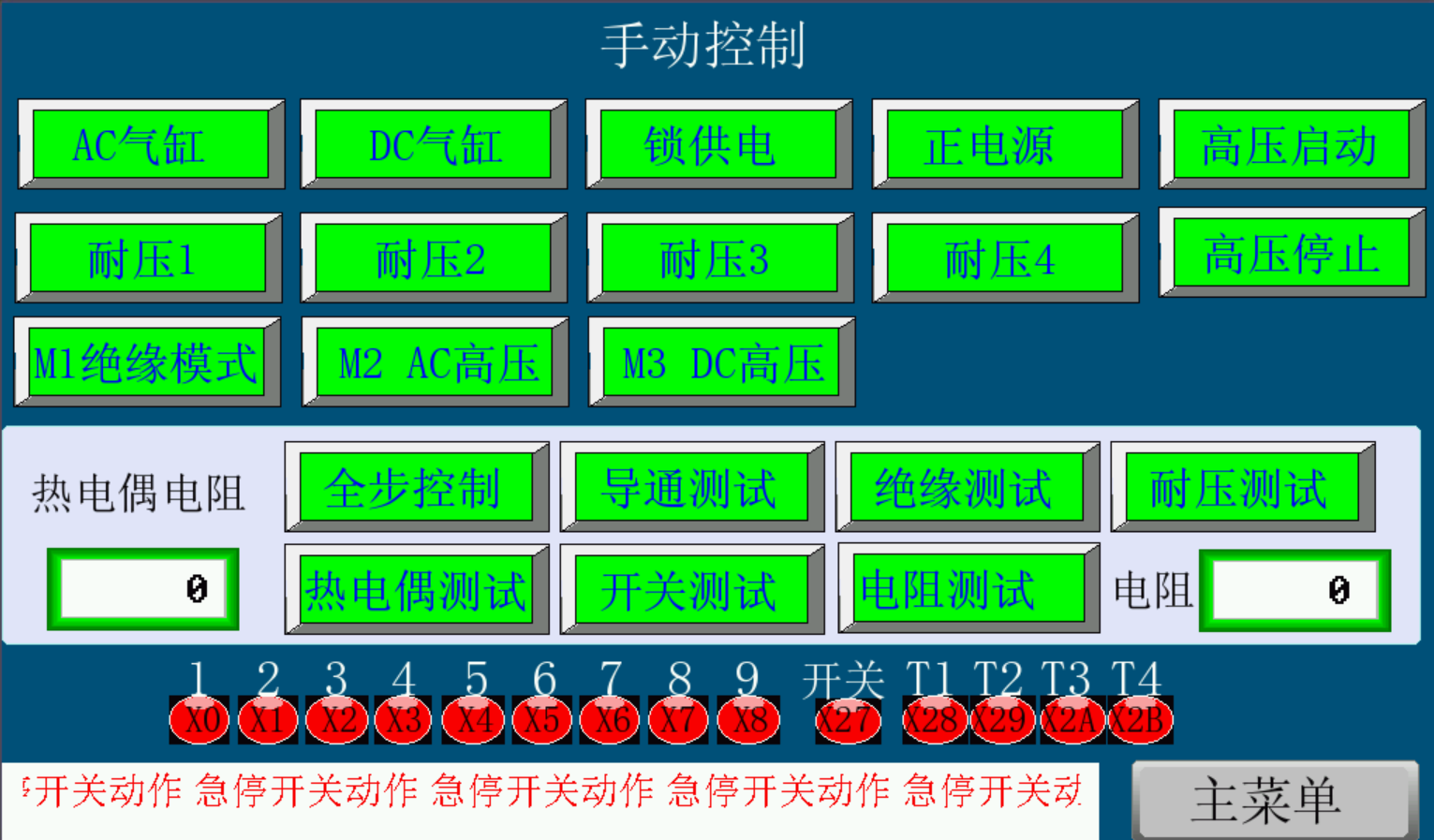
10. Enter the main menu "Manual Control" interface:
Figure (12)
Figure (13)
Manual control: Press the AC cylinder button, then the cylinder presses the gun head button, adjust the cylinder to the appropriate position and fix it.
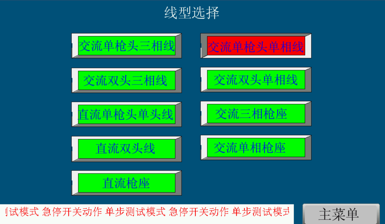
11. Enter the main menu "Line Type Setting" interface:
Figure (14)
Line type selection: AC single gun head single phase line.
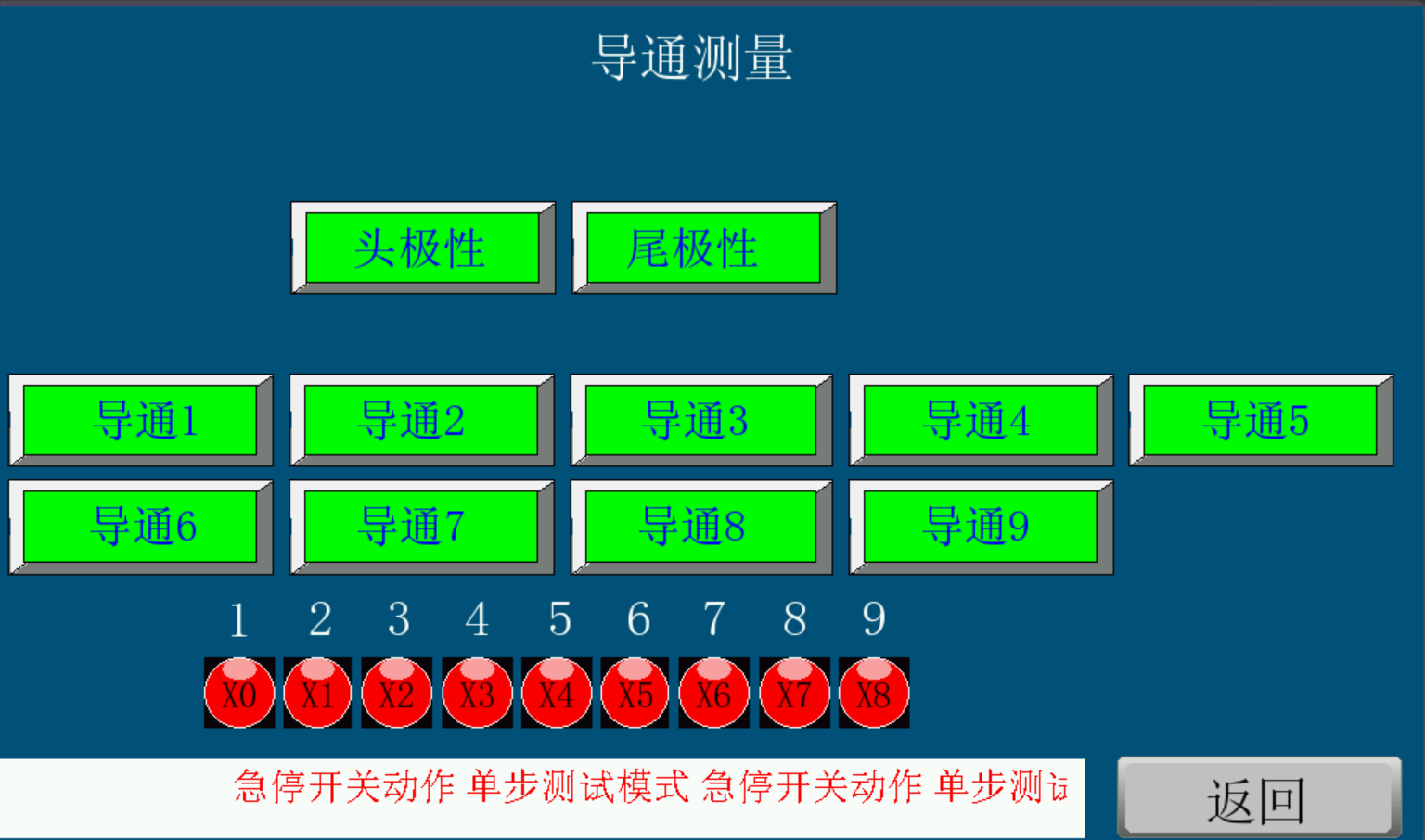
12. Enter the main menu "Continuity Measurement" interface:
Figure (15)
Press the head polarity and tail polarity buttons to connect the head and tail. Then press the test sample connection equipment line sequence button in sequence. Continuity 1 (L1/L/DC+), Continuity 2 (PE), Continuity 3 (N/DC-), Continuity 4 (L2/S+), Continuity 5 (L3/S-), Continuity 6 (CC/CC1/CC2), Continuity 7 (A+/CP), Continuity 8 (A-), Continuity 9 (SIGN2). While pressing this button, you can observe the corresponding line sequence access signal (X1, X2, X3, X4, X5, X6, X7, X8, X9), and it turns green when connected. After determining the conductive line sequence, set the "Function Setting".
[Daily maintenance, regular maintenance matters]
1. Start the device for testing regularly to avoid affecting the smooth progress of the test.
2. This device must be placed in a dry indoor environment without direct sunlight.
3. Corrosive items are not allowed to be placed on the device to avoid damage to the device.
4. After each test, please clean the device in time to keep the device dry and clean.
[Precautions]
After the test is completed, wait for the fan to dissipate heat for 5 minutes to avoid damage to the internal components.