According to the national standard GB16917.1-2014 Residual current operated circuit breakers with overcurrent protection for household and similar purposes (RCBO) Part 1:
General rules meet the requirements of a, b, C (1) of clause 9.9.1.2 of GB16917.1 (AC type)
Test items: (at a reference temperature of 20℃±5℃) The temperature control box is provided by the user.
1. When the residual current increases, verify the correctness of the action: the AC type residual current circuit breaker is at rated voltage, and the residual current starts to increase steadily from 0.2I△N, and the tripping current is measured
2. Rated residual current, verify the breaking time: under the rated current of the AC type residual current circuit breaker, simulate the closed circuit breaker, and test the breaking time.
3. Sudden residual current, verify the breaking time: under the rated current of the AC type residual current circuit breaker, simulate the closed circuit, and test the breaking time.
The test bench equipment consists of four parts:
1. Test equipment control unit and interface unit.
2. Residual current test bench.
3. Circuit board test fixture.
4. Single chip microcomputer control.
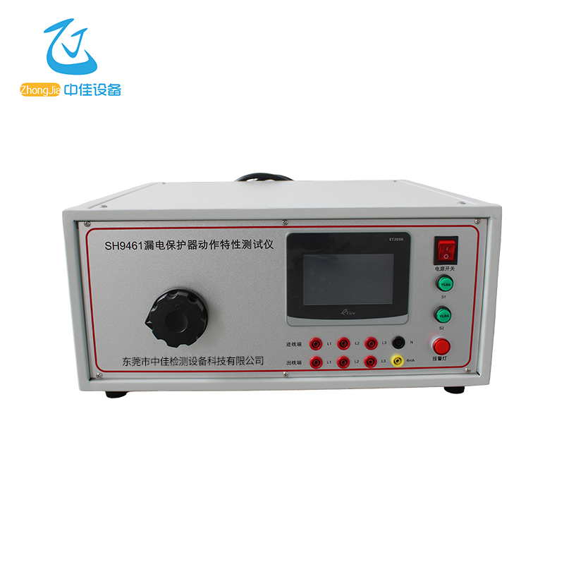
Complete machine picture
Figure 1
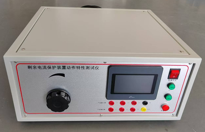
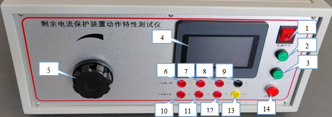
Panel layout and function description
Figure 2 (Control panel)
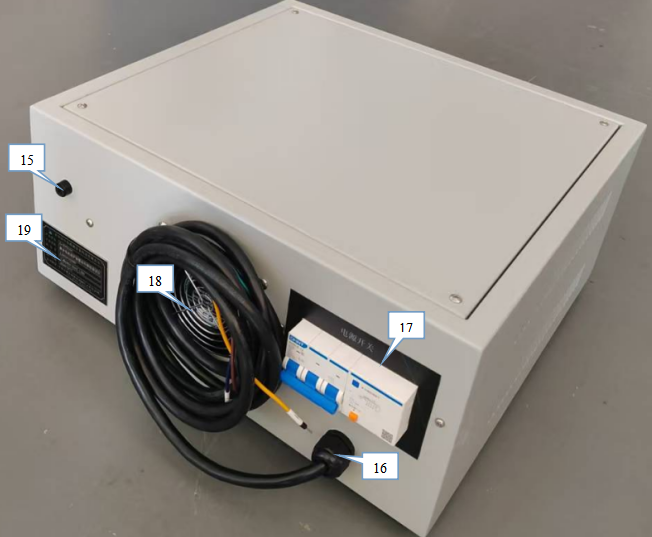
Figure 3 (Back)
1. Power switch: Press to start.
2. S1 switch: Press S1 switch to start the test.
3. S2 switch: S2 switch, (press before S1).
4. Touch screen control: set test mode, parameters and monitor test results.
5. Voltage adjustment: rotate clockwise to adjust the required voltage.
6. 7. 8. Inlet: three-phase live wire output: L1, L2, L3 correspond to touch screen phase line output, see the operation method for details.
9. N: neutral line output (power supply end).
10. 11. 12 Outlet: load end output: L1, L2, L3.
13. 6mA: 6mA output positive end.
14. Alarm light: alarm when the test product fails.
15. 6mA fuse: internal 50mA fuse.
16. Three-phase 380V power input.
17. Cooling fan.
18. Main power switch.
19. Instrument label.
Instructions
1. Equipment power connection
2. Turn on the panel power switch, the touch screen enters the standby interface as shown in Figure 4, click to enter the test, as shown in Figure 5
Figure 4
Figure 5
2. Product connection:
Single-phase: Connect the product to the device as shown in Figure 2, L1/N are connected to the product input terminals L and N respectively, and the product output terminal L is connected to the panel test port
Three-phase: Connect the product input terminal to the device L1/L2/L3/N, and the product output terminal Ln (Ln is the phase selected by the touch screen) is connected to the panel test port.
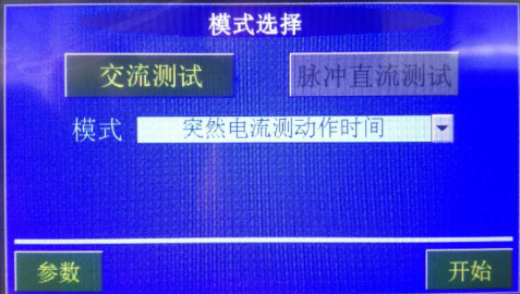
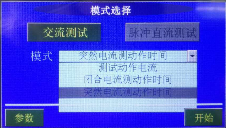
3. Test mode selection as shown in Figure 6
AC test Click to select AC test Mode selection Test action current
Figure 6
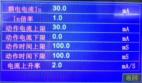
4. Parameter setting Click parameter setting to enter the parameter setting interface, set parameters according to standard requirements, rated current: product rated current, In ratio, action current upper limit, action current lower limit, action time upper limit, action time lower limit, Current rise rate. After setting, return to the phase voltage setting interface as shown in Figure 7
Figure 7
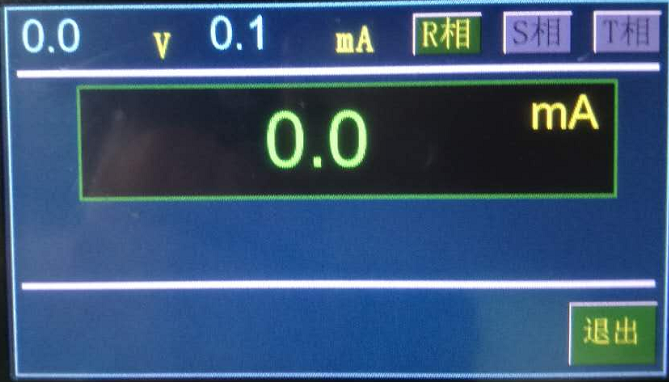
Figure 8
Press the S2 and S1 switches, adjust the knob cap of Figure 2 (6) on the panel, and observe the voltage display in the upper left corner of Figure 8 until the required voltage is reached. Click to select the R/S/T phase in the upper right corner (corresponding to the back input L1/L2/L3 and output L1/L2/L3). The panel test port needs to be connected to the live wire of the output end of the corresponding selected phase of the product.
5. AC test
Test action current: Close the product, press the panel S2 switch and S1 switch in turn. The current increases at the set rate until the product trips. The trip current is shown in Figure 8
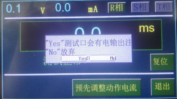
Close current measurement action time: Enter the interface of Figure 9 below, pre-adjust the voltage to the required value, click Pre-adjust action current, and the selection interface pops up, select YES OK. Automatically pre-adjust to the set current.
Figure 9
After the current pre-adjustment is completed, put the product in the off state, press the panel switches S2 and S1 in turn, and the two switch indicators will light up respectively. Close the switch quickly, and the device output starts timing. It will be qualified at the set time.
Sudden current measurement action time: set parameters and pre-adjusted current with the closed current measurement action time. After the pre-adjustment of the current is completed, close the product, press the panel switches S2 and S1 in turn, and the device starts to output voltage and counts until it trips. It is judged to be qualified within the set time. Otherwise, it is unqualified.
6. Pulse DC test parameter setting
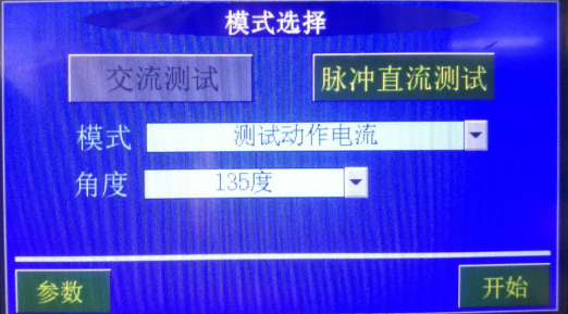
Test action current Click to select Pulse DC test, mode selection Test action current, and test angle, as shown in Figure 10
Figure 10
Set parameters according to standard settings, and the wiring and voltage setting methods are the same as AC settings.
7. Pulse DC test
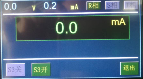
Test action current test Press the start button to enter the voltage setting interface, as shown in Figure 11
Figure 11
After starting, pre-adjust the voltage to the required value, select S3 to open, close the product, and press the S2 and S1 switches in sequence. Until the product trips, it is judged to be qualified within the set time. Select S3 to close and repeat the previous test. The test is completed.
Sudden current measurement action time:
Set the test parameters, pre-adjust the voltage and test current, select S3 to open, close the product. Press switches S2 and S1 in sequence. The device outputs and counts until it trips. Select S3 to close and repeat the previous action. The test is completed.
Note: If 6MA current needs to be superimposed, connect the neutral line of the product output end to the 6MA terminal of the panel.